I recently came into possession of a grinding wheel balancer, and having fun with the digital camera, recorded the exploits. Prior to, I didn't know much about balancing grinding wheels so thought that maybe posting on it would help some people. The basics i learned via Jan Rowland's article at
http://www.homemetalshopclub.org/news/sep04/sep04.html
some good info there on making your own.
It may or may not help on a bench grinder but on the T&C cutter grinder or surface grinder it can make a real difference.
Here's a nice balancer that came my way. I was surprised to find its metric, $38 for metric die to make a new foot that was hopelessly bent.

I barely had enough room to start a tap with making extensions and once started had to use a wrench. The pillar tool is used to make this awkward start straight.

here's the finished arbor. I must have had a hole go slightly off or some thing as the plate shown need a tiny bit of balancing itself.

next it's the balancing weights. I made them from two thicknesses, .025 and .031. I wanted a very accurate fit on the arbor so that error wouldn't induced between disassembling on the arbor and installation on the grinding spindle. The four sheet metal pieces are sandwiched between a couple of metal plates

After boring, I laid out, sheared and then filed to shape the weights.
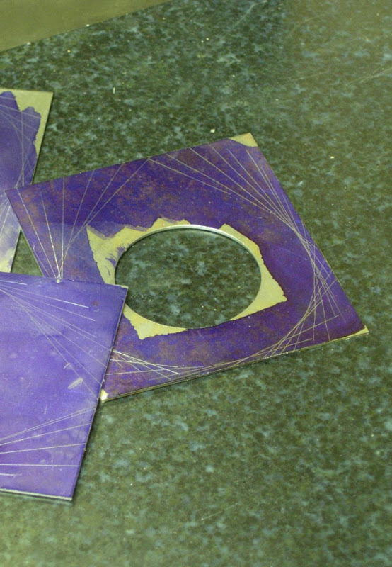
here are the finished weights, identified by number. The number will help get it right when its reassembled on the spindle.

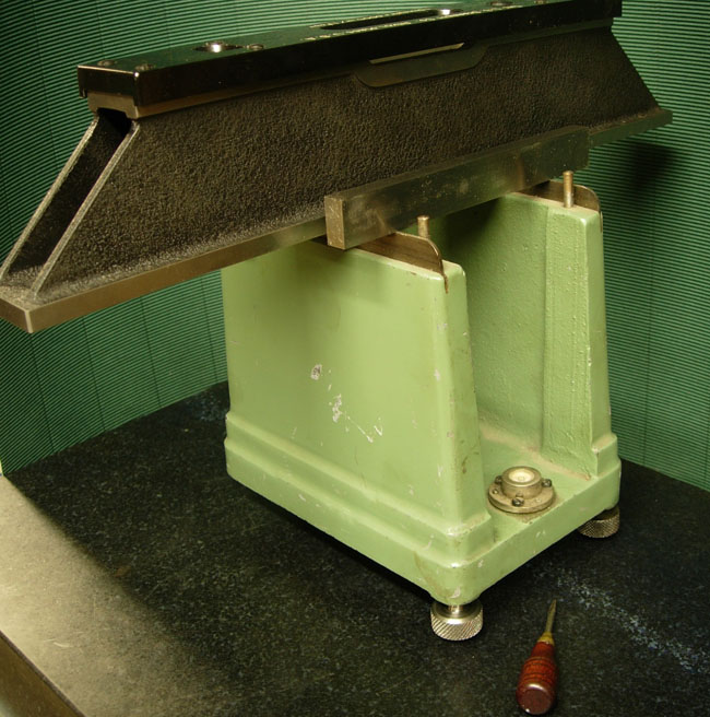
the balancer's got a small internal level. I checked and adjusted this with a precision level, will probably do this each time, the internal level is not super sensitive.
here's a final shot of it in use. The location of each weight is marked on the blotter and then its reassembled on the grinding spindle.
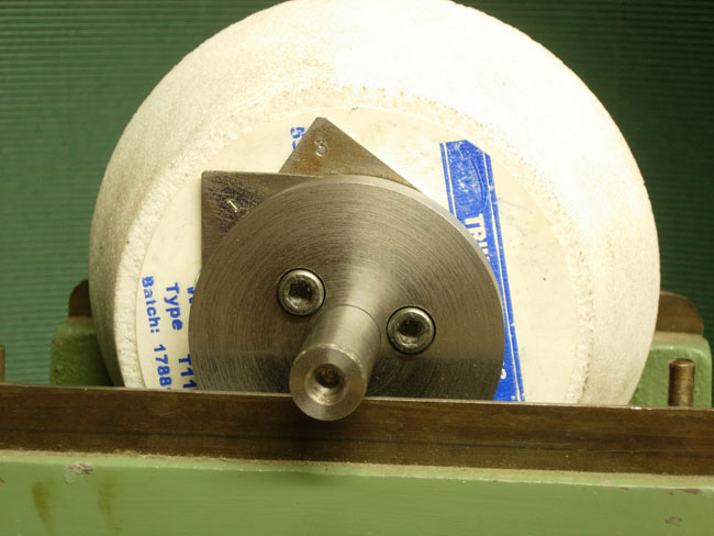
The wheel shown, a 'triumph' which I think is KBC's house brand and was in terrible balance, causing noticeable vibration in the machine and on the cut. After balancing, it runs as smoothly as the spindle does empty!
Here's the article that Mcgyver linked to (actually written by Dick Kostelnicek):
Static Balancing of Grinding Wheels
by Dick Kostelnicek - HMSC Member

What you Need
A 9 x 12 in. surface plate.
A set of 1/4-in. thick parallel pairs.
A precision level.
Two 6 in lengths of undamaged 1/4 in. drill rod.
Super glue and masking tape.
A mandrel or arbor that fits your wheel.
Time and patience
You can statically balance vitrified grinding wheels for both your surface and pedestal grinders with a few common shop tools. Don't worry about dynamic balancing. These wheels don't need it since they are large in diameter compared to the axial thickness and they don't change shape when turning at rated speed. First, build two arbor supports from pieces of ground parallels, as shown in the photo below. I place a very small drop of super glue on each end of a parallel as I stack them on top of one another. Later, you can disassemble them by breaking the glue bond and cleaning the residue with acetone, an excellent solvent for cyanoacrylate glue. Use masking tape (colored blue in the photo} to secure the drill rod to the top of each stack. The round drill rods prevent the sharpness of the edges on the parallels from interfering with the free wheeling of the wheel arbor. Also, debris will be easily squeezed out from under the arbor while rolling on a round rather than a flat surface. Make sure the surface plate is perfectly level in both directions. My plate is supported in a metal frame that has three adjustable screw feet, making it easy to level.

Surface Grinding Wheels First, dress the wheel while mounted on the machine for which it is to be used. This will guarantee that it is round, a necessary step for new, inexpensive, or damaged wheels. Then, mount it on a dummy tapered arbor (see photo below). For balancers, I use a pair of thin spring shims. They are made from 1/8-in. aliminum sheet, split at the bottom of the large hole, and clamp over the wheel hub.

Now, place the wheel arbor on the two supports and allow it to settle to its heavy point (without shims). Mark the high spot of the wheel, calling it the light side mark or LSM, on the edge of the round paper blotter. Then, mount the two shims with their projections perpendicular to the LSM as seen in the photo below.

Rotate both shims in opposite directions a few degrees toward the LSM. Roll the wheel so that the LSM is parallel to the surface plate, and let it settle to its heavy side, photo below.

If the LSM is still on top, move both shims closer to the LSM until the wheel will not rotate when the LSM is turned parallel to the surface plate. Some times you may not rotate both shims by the exact same amount in opposite directions. Then the LSM may not be at the top or bottom after the wheel settles. In that case, move just one of the shims to reset the LSM vertical. This will take some practice, as you will always choose the wrong shim to move or move it in the wrong direction. When the wheel stops rotating at an arbitrary point, well almost any point because you have to stop when it is good enough, then you are done, as seen in the photo below.

Pedestal Grinding wheels The photo below shows an 8-in. pedestal grinding wheel to be balanced. I use a lathe mandrel having a very slight tapered, but that is of no consequence here, to support the wheel and its metal wheel flanges during balancing. I've lightened up one side of each flange by drilling a few holes near the edge. Now the side without holes is the heavy side of the flange and plays the same role as the weighty projection of the clamp-on flanges discussed above in reference to surface grinding wheels. Here, however, you must place one flange on each side of the wheel. Just as discussed above, start without flanges to determine and mark the light side or LSM of the wheel. Place the flanges against opposite sides of the wheel so that the lightening holes are along a line parallel to the surface plate and facing toward opposite sides of the wheel. Now proceed to counter rotate both flanges so the lightening holes move away and downward from the LSM. Stop when the wheel settles at an arbitrary point.

Witness mark the flange against the LSM on each side of the wheel as seen in the photo below. Finally mount the wheel and its flanges on the machine's arbor and spin it up to speed for a test run.

Now, as will often happen, the wheel flanges will not be snug on the dummy arbor during balancing. They may try to always settle to their heavy side while you are rotating the wheel. You may not notice the slippage of the flange as the wheel is rocking to and fro. This can lead to great frustration. Solve this problem by putting a bit of chewing gum between the flange and the wheel. Or better yet, upset the inside of the flange arbor holes with a prick punch as seen in the photo below. Either of these two methods will provide enough friction and prevent the flange from rotating relative to the grinding wheel on its own.

I hope your wheels run with reduced vibration. You may even see less waviness on the surface finish of the items produced on your surface grinder.