One of the most gratifying tasks we modelers can undertake, is the construction of our own tools....at least this is my personal way of seeing things....
A long caressed project from way back then, was the design & building of a finger plate....I just made the decision of making one for my use....since I used one of a friend of mine, I now wonder how I did without it....
I made a thorough search in the web, not finding much, but what little I learned I added to my personal needs....so here we go....
I started with the base, which I produced from a discarded PC aluminium heat sink, from which I hacksawed the fins and made a long and boring flycutting sesion....
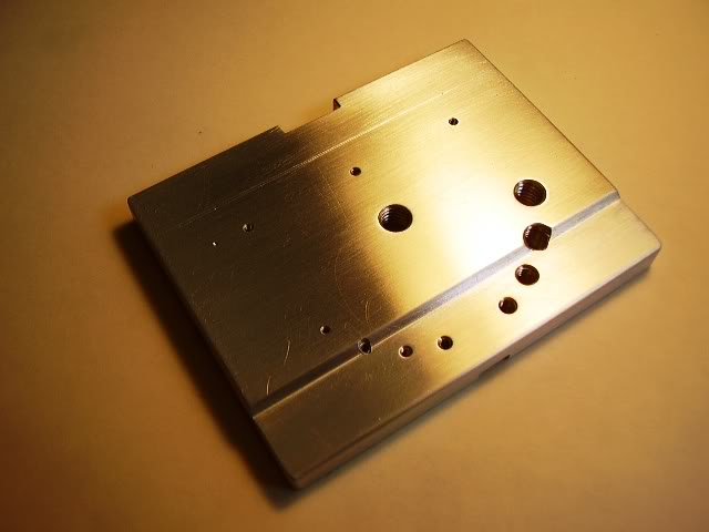
Here it is, finally sanded and polished....the four sides are at exact 90º from each other so it can be used in my milling table and in the miniature table saw....

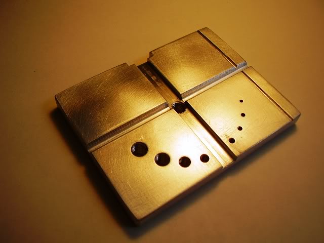
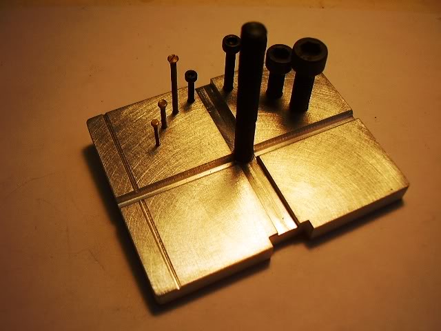
Notice that the upper face of the base has 3 milled "V" ways for holding different size round material...also there are 8 threaded holes which are mighty useful for holding the most used screws or bolts I mostly use in my models....these are from the smaller up....1.2 mm, 1.4 mm, 1.7 mm, 2 mm, 3 mm, 4 mm, 5 mm and 6 mm.
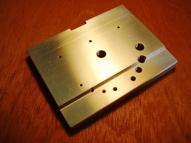
The bottom face of the base....
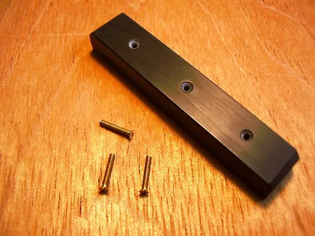
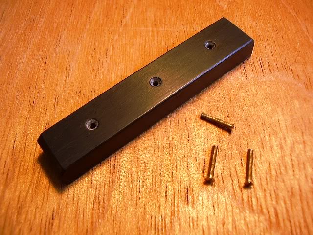
If you should want to use the finger plate on the vise, a screwed bar was devised which is applied via countersunk brass screws from below...
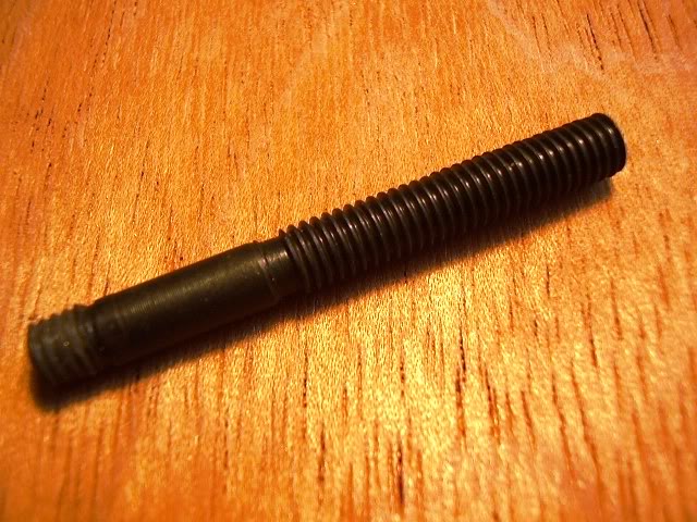
The pillar, made from BMS and threaded M6, the lower threaded portion is made in such a way that you can fix it to the base with just finger pressure....I intend to make a wooden box in a time to come to keep the whole safe & sound.... so the pillar must be removable...besides I love making special wooden boxes!!!!
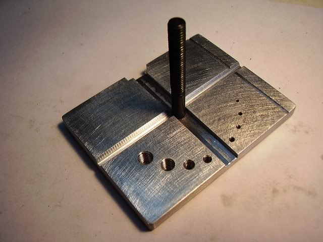
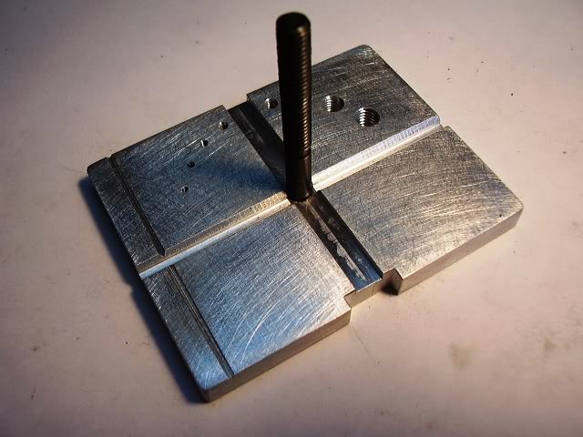
The pillar in place on the base...................
The clamp, made from 4 mm thick brass.......the lower ends are slightly angled so they can rest parallel to the base when in use....


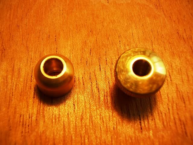
The clamping knob & the special washer.............


The special washer that goes under the clamping knob, is rounded on the undernath so that it gives good grabbing power at any angle......
The adjuster screw...........Made from an M 4 bolt, with a heavily knurled brass knob, has the added finesse of using an acrylic point so as not to marr the plate's surface when tightening it..........


Here's an image of the threaded holes being occupied with an example of each bolt of different dimensions....
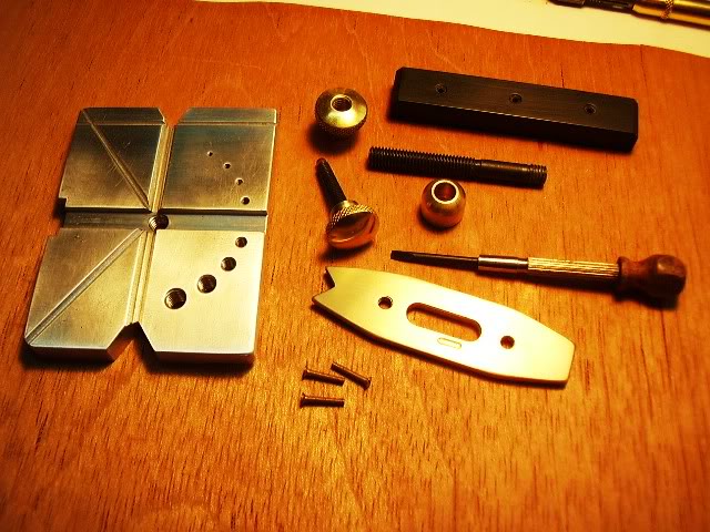
The parts of the ensemble, including a special screwdriver to screw in the special base for using it in the vise....
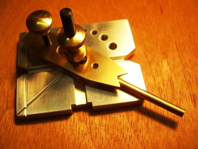
The finger plate assembled showing some of its infinite uses.....
A brass bar in one of the "V" ways, ready to be crossdrilled....

The same brass bar in one of the corner "V" ways, ready to be filed or rectified via a grinder....
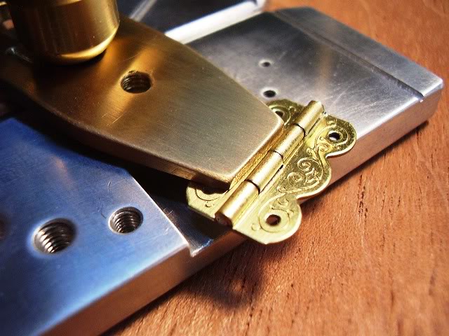
A small hinge to be filed......the clamping action of the finger plate is really powerful, when it bites.....well........

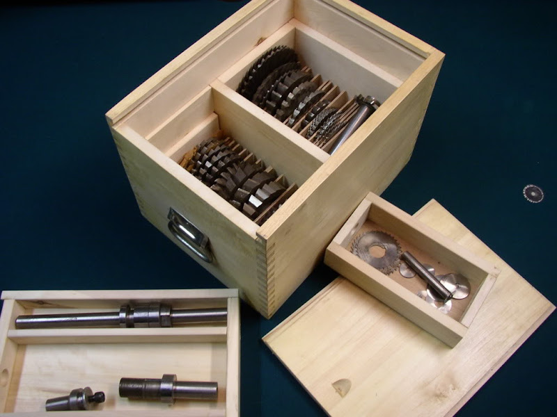
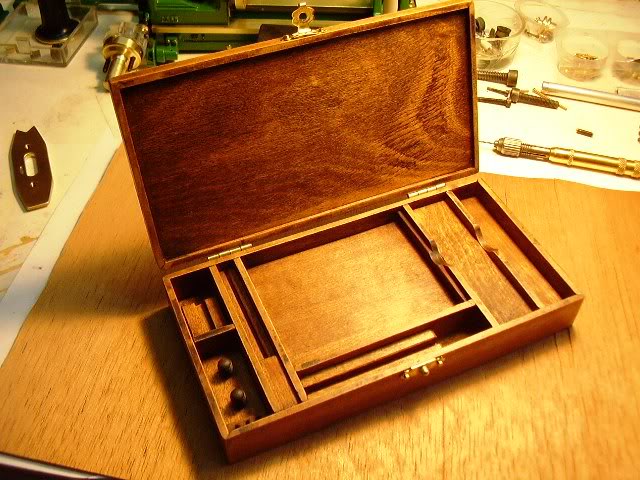
The finished box with all its inlettings.....
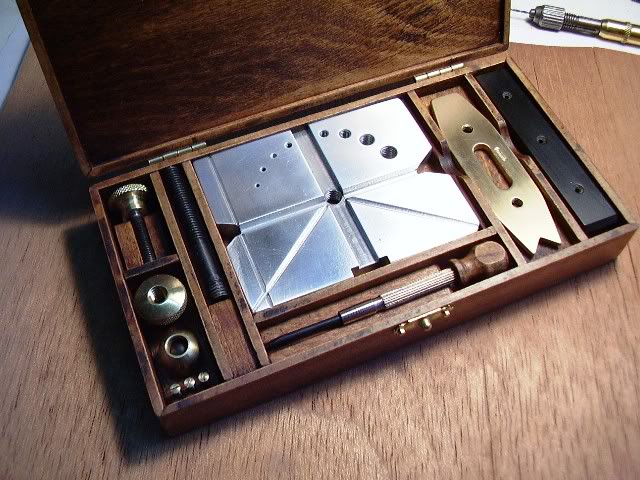
The box with its contents....

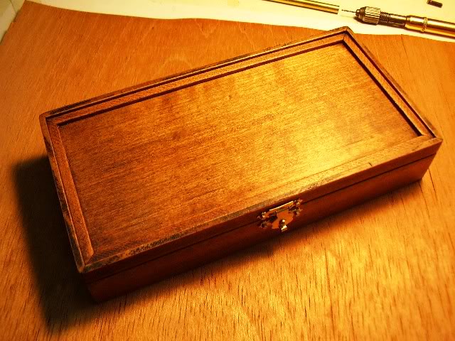
The closed box.............by the way, the box was made entirely in 3 mm thick plywood....

Another homemade tool for the collection............