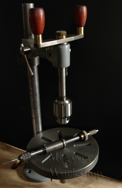
Jerry Howell has plans for a Mini drill press

and a Micro drill press
Some YouTube videos of a mini drill press:
Video 1
Video 2
Video 3
There's also a sensitive drilling table in Projects 1 by Village Press:

And then there's George Thomas' Universal Pillar Tool.
Building links here and here.
The following ME articles are the ones I could find regarding the UPT:
Vol Issue Page # Title Subject
140 3501 1104 1 Tapping machine and staking tool - General arrangement
140 3502 1165 2 Tapping machine and staking tool - Arms & spindles
140 3503 1209 3 Tapping machine and staking tool - Staking tool
141 3510 351 4 Tapping machine and staking tool - Further details
142 3548 1078 5 Tapping machine and staking tool - More details
142 3549 1149 6 Tapping machine and staking tool - More details
146 3647 1504 1 Mini Drill for Tapping and Staking Tool - Introduction
147 3648 12 2 Mini Drill for Tapping and Staking Tool - Main arrangement
147 3649 86 3 Mini Drill for Tapping and Staking Tool - Sleeves
147 3650 143 4 Mini Drill for Tapping and Staking Tool - Feed lever
147 3651 218 5 Mini Drill for Tapping and Staking Tool - Handle
147 3652 295 6 Mini Drill for Tapping and Staking Tool - Conclusion
Mcgyver posted about his UPT on the HSM and the HMEM forums:
hadn't posted many pics lately, so a few weeks ago i snapped up a bunch of my UPTI experimented a bit with the photos – its just a black piece of cardboard with the shop lights off and sunlight through a window. Camera is a P&S Nikon P3 (I affectionately call it my POS P&S). It does have the advantage over other P&S that you can control aperture. Everything is done with a tripod and no flash. I also put my name on each pic, what the heck, I made ‘em
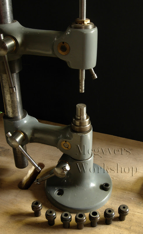
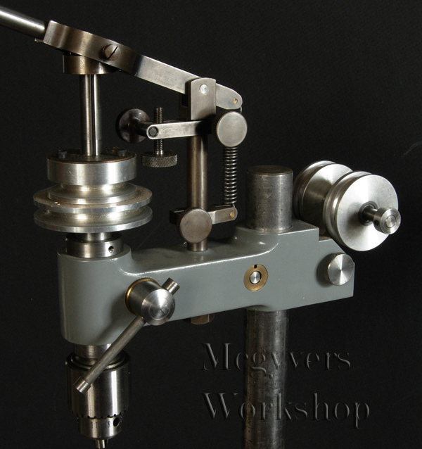
The project is the Universal Pillar Tool, a classic designed by George Thomas. I went full bore and made all the accessories including the sensitive drill head.
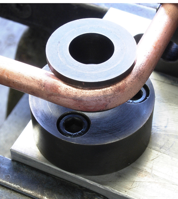
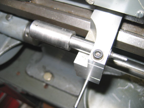
Here’s a smaller tapping head. For the newer guys, not breaking taps depends on keeping them straight so this tool is very handy. I used the end off an Eclipse pin vice of some sort, but still had to make a collet to fit common small tap dia. The bushing in the arm has a small spring underneath the threaded brass cap that presses light on the rod – very handy as the tapping head stays where you leave it and doesn’t fall into the work.

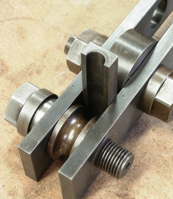
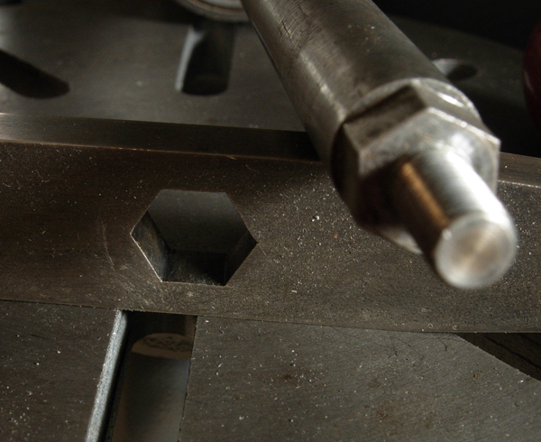
Here’s a close of the small tapping head handle showing the “D” coupling. This is my design and gives and positive drive without having to tighten anything. It’s a snug fit, won’t fall off accidentally.

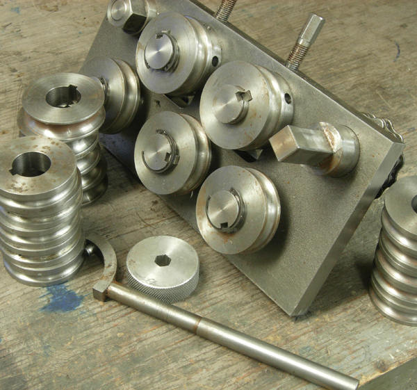
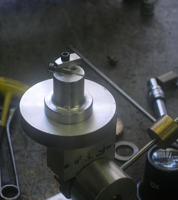
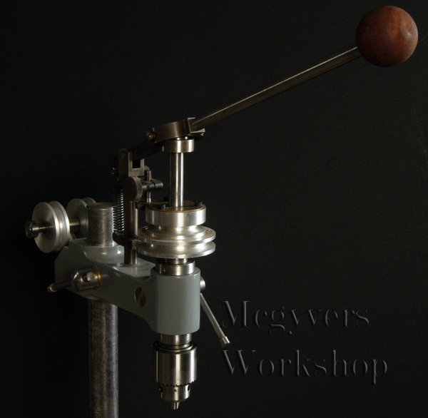
Here’s a larger tapping head
It’s handle is held on by a hex I laid out and hand filed. I’d heard filing hex’s that fit perfectly in each position was the sort thing they’d assign apprentices to teach them to file so thought it would be a good test. It fits amazingly well, the secret is to use a bit of blue as you’re getting close and be very specific about where you are removing material
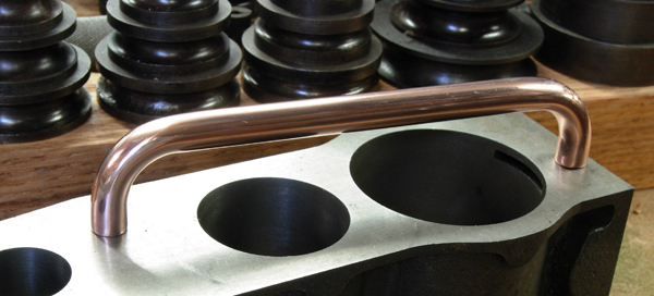
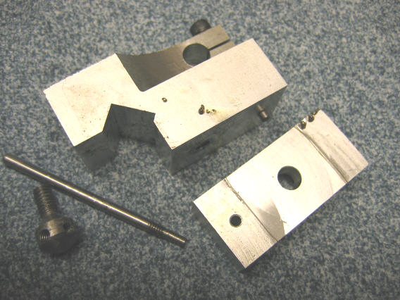
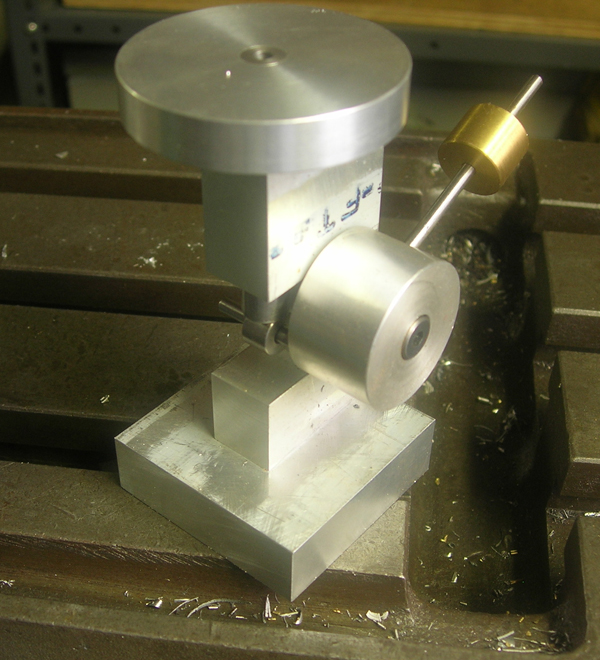
Reconfigured a bit, the tool becomes a staking/riveting tool. Here a couple of blank tools are shown.
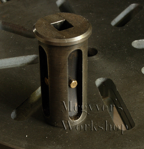
Similarly, a square bushing holds number/letter stamps

The bushing for the square punches is interesting – there are two springs with detent balls underneath to hold the punches in place – a very nice feature!
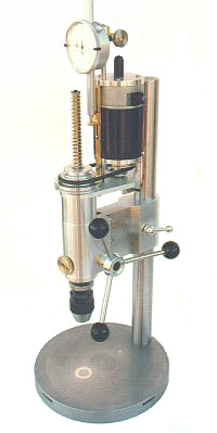
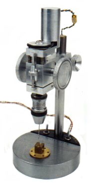
The most complex accessory is the drill head. It works very well and is a pleasure to use. There is an extra casting for this kit but they wanted a fortune for it so I carved my own.
Here’s a close up.
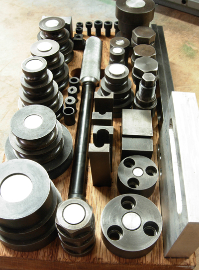
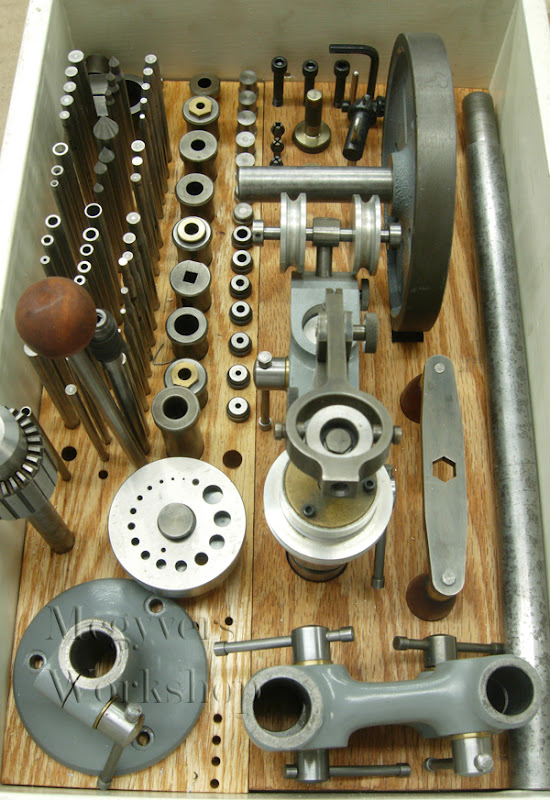
Lot’s of accessories to make. This photo’s a little dark, I still need more exposure experimentation I guess. Most of the staking/punching tools are made but not yet hardened.

It resides in an old drawer with a lid. Hey at least it keeps the condensation off. One day a better made box will get done
Hope that was of interestCastings were bought eons ago, maybe Power Model Supply when they were around? can't remember. They are still available I believe, check with model engineering suppliers. While cast iron is nice, you could make the whole thing from bar stock like i did the drill head.
Andy, here how i made the D shape. take a piece of brass, say 3/8 dia. Boring the bottom 1/2" to the D's ID radius, milling a section a away, soldering on a flat piece. now, back to the lathe, and turn the OD to neatly drop into a bore in the brass handle and solder (or loctite). if you look at the pics you can see the the lines that shows these fabrication. Hard to explain the drill mechanism with a reasonable amount of typing and my camera is currently busted. I'll take some detailed pics when i can. basically there's a gimbal with a bearing at the top with a radial groove in it. two pins in the gimbal fit into this groove (you can see them in the last pic),
Norm, I have that book, always thought it was basically a reprint of Thomas's two other books? anyway, I like it. Also, years ago HSM did a excellent build article that appears in one of the project books. There'd be minimal welding if you didn't make from castings, for example the arms could be machined from say 1.5 x 1.5 steel stock. Our be luxurious and get some Durabar.
The other note i'd make is I went with peened over tommy bars throughout. This is a departure from the traditional ball handle which is more difficult to make and by many's standards the 'right' way to do it. imo the tommy bars are superior as the can be operate from two positions and there are lots of pinch point set ups where this is a real advantage, the traditional charm of ball handles not withstanding.
LizardKing posted the following:
For all the Americans interested in one of these, I bought a full set of castings from http://www.martinmodel.com/ a few months ago.
Quality if really good and he does have more at around $100 plus shipping for a set which includes 2 arms, table, base, and drill head.
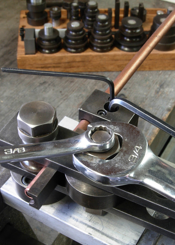
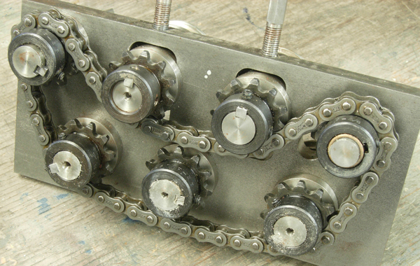
Mcgyver posted again about his UPT on HSM showing it's use for stamping metal: you're right, how many otherwise great looking tools look amateur hour with crooked stamping. A friend who apprenticed at GM recalls a 2 week stint in the stamping shop....no one came out of there not being able to stamp straight. How do you get to Carnegie hall? practice practice practice not wanting to spend two weeks practicing, there's Geo Thomas's UPT which has a great component to it, a square holed holder with detent balls and springs so the punches don't drop out. Clamp a fence to the table and by hand slide the work along for perfectly aligned stampings. Any two pieces of metal together can form the corner....figure out how to hold the corner above table with fence and away you go. Here's some pics of a recent project just for fun - using the UPT clamped to the mill table to mark graduated dials
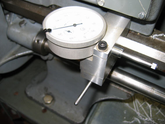
aligning things


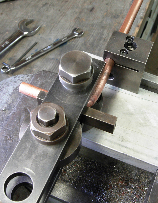
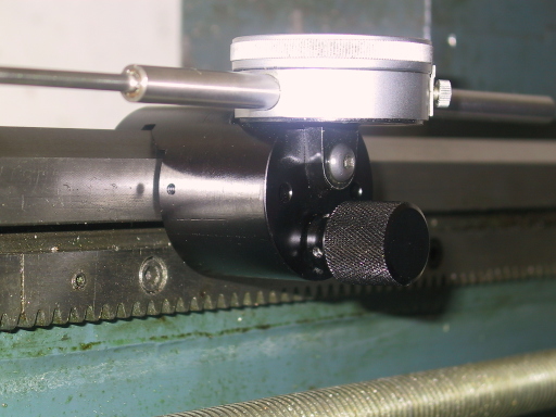
punching

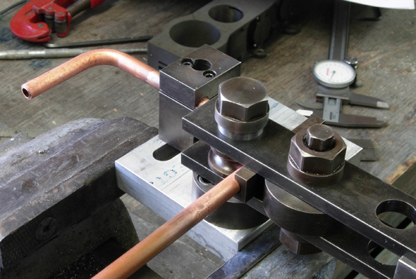
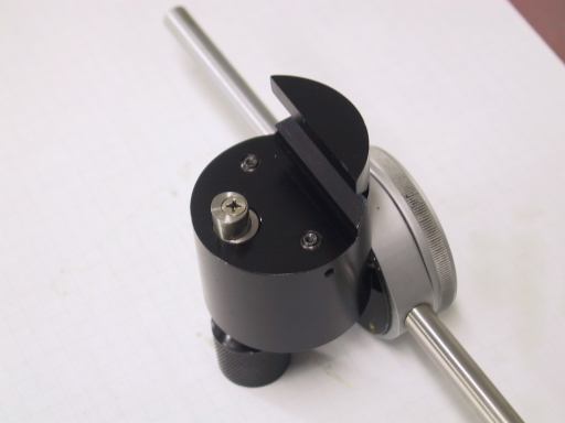
results...things more or less straight!