There's a good thread on the HMEM board talking about polishing and finishing models:
I am assuming that you will be final polishing with a buffing wheel. An unstitched linen wheel and very fine buffing compound, plus some vienna lime to finish off.
Nothing looks worse on models that are being displayed as machining marks.
We all get them, some a bit worse than others. The way I look at it is that if it takes me an hour to machine a part, it will most probably take me two hours to get it to a stage for polishing. Remember polishing, because unless you get your metal smooth, polishing it will make it worse.
The only correct way to get your metal prepared is to imagine a ripe soft fruit on the tree, with not a blemish on the skin, if you can get your metal to this stage, it is then ready to polish, not before.
No easy way around this, pure finger aching, skin blistering hard work.
I use a combination of files starting from smooth to almost a plain piece of metal, none of your one swipe to remove 1/2" here. On brass and ali I do a lot of scraping on the faces, an old hacksaw blade with the teeth ground off, then the edge honed on an oilstone to get it totally flat will work wonders when dragged along a rough machined face, square HSS blanks will do the same job, so will your neighbours best wood chisel. Then finish off with finer grades of either wet or dry paper or emery cloth, not held in the fingers, but wrapped around somehing solid. If you use your fingers you will get hollows forming in the edges, not noticeable at this stage, but after polishing will look awful. This is just on the edges, now for flat faces.
You have got to keep flat faces truly flat, with nice sharp edges.
Again the way I do mine is use a hard flat face to work from. You have all seen my tapping fixture that I also use for taking pictures on, well that started life as a small surface plate, so that is my flat surface. Yours could be a very smooth worktop, or like I used to use, a glass plate out of an old photocopier, or go to your local glass merchant and get a piece cut to about 12" square, but ask him to smooth the edges for you.
What you are after for your metal is a perfectly smooth flat surface with very sharp edges.
I use masking tape to stick down sheets of abrasive paper, if wet or dry I put a couple of drops of oil on it to keep the cutting edges sharp. Normally I will start with 400 grade and work my way up to 1200. No backwards and forwards or side to side on this operation, it will introduce a curvature to the flat face. The method used is a lapping technique, whereby you move the job in a figure of eight motion, keeping a steady downwards pressure. After a time you will get into a rhythm and will soon eradicate those annoying marks. Perfection takes time.
You should finish up with a nice, matt, smooth as a babies bum with very sharp edges. Now you can polish it.
The reason you do not polish out machining marks with a buffing wheel is that after you get the marks out, the surface finish will look like a bendy mirror in a sideshow stall, and the corners will look like they had been done with a roundover bit. Not what we are after. If you prepare the metal as I have said, polishing with a wheel will take seconds and the job will look like it has been plated. That was for work with flat or miller cut radii. For round bits done on a lathe, it is usually rather a lot easier because you can get the machine to do the work for you.
If you are smoothing curved bits on the lathe then using loose emery strips or wire wool or scotchbrite, work over gently by hand, being very careful about getting near to the chuck, we are trying to polish, not paint red. For straight areas or large inside curves wrap emery around a flat piece of softwood or round dowel and use it in a filing motion to polish the surface. Again when all machining marks are gone, a few seconds on the buffing wheel will really make it shine.
This was a brief description of how I manage it, other people have different methods, and I hope they will post them here.
Now a quickie from me. I have been building models for many years from wood and plastics and I can get a great paint finish on them, but getting the paint to stick to metal correctly and achieve a showroom finish has so far eluded me. This would make a fine next post.
John
From Cedge.
John
When I first began researching the machinist forums, I often encountered the question, usually asked by a newbie... How do you get a mirror like finish with a final cut?. The answer is always the same... You don't get a mirror finish from a final cut. You have to do it by hand. I do things pretty much as you've described, but my finest wet dry paper is 2500 grit and I've got a few sheets of lapping paper that go as fine as 3 microns. I finish things off with a metal polish called MAAS, which is somewhat like Flitz or SimChrome. It seems to give me a better finish on more types of metal than the other two products.
Flat surfaces get lapped. You can do light touch up with a finger, later, but an nice even flat surface finish requires lapping on a nice flat surface. Here is a another tip that no one thinks to tell you. When lapping or sanding aluminum, use a bit of WD40 on the paper. As you work the piece, a gray paste will begin to form, created by the combination of lubricant and aluminum dust. This paste will begin to load up your sand paper pretty quickly. Many users would exchange this slick sheet for new paper when this happens. However, this is when things are just beginning to get right. Here's why.
Aluminum oxidizes as soon as air hit it. This oxide coating is of the same chemical make up as sapphire or ruby, which are next to diamond in hardness. The best grades of sand paper or emery are made with... Aluminum Oxide(silicon carbide). As the sand paper sheet loads up it is also quickly becoming a very high grade, super fine grit abrasive which is excellent for fine finishing metals. Don't throw the paper away... put it in a plastic bag to keep it dust and swarf free for use, not only on aluminum, but brass, copper, bronze, steel, cast iron, even stainless.
When polishing out tool marks on the lathe, use a sanding block. Its flat surface will prevent those finger induced ripples. The sanding block also gives you something substantial to grip a bit removed from those spinning jaw chucks. I begin with 100 grit to knock off the high ridges and then follow on with 220 grit. then I jump to 400 or 600 before using 1200 and 2500 grits. I also use MAAS, but great care has to be given to keeping the cloth from mating with the spinning chuck jaws. Never warp a finger or hand in the cloth and only hold it so that if it should snag, it will easily escape your hand and you do not follow it into the vortex. Simple rule... rags and chucks don't get along well. Keep trailing ends well out of reach of those snarling jaws. You need to know where all your digits are and where the rag is at all times. One lapse of attention is all trouble need to invade the scene. If you aren't comfortable with this step, don't do it. It is potentially dangerous if done carelessly.
Don't underestimate the value of a Dremel tool and polishing felts. They can make working in a contour or a recess a lot less of a headache. A Dremel felt and MAAS will make short work of difficult access spots. I typically prefer hand polishing, but I'm not going to work harder than is required for good results.
Like John, a good shine is what tells me my engine is truly completed. It only takes a bit more time, but the results are a huge plus, well worth the little additional work it requires.
Steve
Some real good tips there Steve.
I would just like to add that using a buffing wheel or hand polishing is purely a personal choice, they both give the same results. A deep lustre, that when you look onto a flat polished surface it should be like a mirror with little or no distortion.
Now I forgot about his question when I asked about the paint job. Laquering polished parts to retain the shine. But please try to keep any answers to a neutral product range, not all commercially named products are marketted worlwide. I am fed up of stripping down engines to give them a once over.
John
From Gilessim
I've found that the 2 component paint that they use in car body shops now seems to work well even without primer on small bits, the new stuff is also water-based so doesn't stink!, usually the local car body shop will give you a drop in an old can if you ask nicely!, if you put enough paint on ,any blemishes can be "cut out" using fine paper and water as described for polishing metal above, as this type of paint dries very, very hard, though I would leave out the buffing wheel stage on the metal before painting.
Ally ,on the other hand is more tricky, as you should use what is known as "self etching primer" to get it to stick, I don't have any experience with this although I've seen it used and I expect that these days there are new products to prepare the ally first...Giles
From Compound Driver
HI
Ok heres how I brush paint a traction engine. My first requirment from a painted surface is a glass smooth end result with no brush marks runs or dimples.
The first primer coat is always an etch primer brushed and not sprayed. Pheonix precision paints in the UK do a superb single pack etch that goes on really well. This coat is left for a few days to harden fully. I then apply a coat of red oxide primer and let that dry for a few more days.
I next apply a second coat of red oxide and after two days flat that back with 140 grit wet n dry almost to the gray etch primer. The third primer coat then goes on with long even brush strokes side to side on the item being painted. Again two or three days between this coat and the next.
The first colour coat now goes on again full length strokes allowing the paint to flow out from the brush. Once this coat has had seven days to harden fully I rub down with 140 grit to the point that almost all the colour has gone leaving mostly red oxide.
This procedure is carried out a further half dozen times taking less paint away each time. At the end of the six or seventh colour coat the surface will be blemish free and almost good enough to be happy with. At this stage I go to 400 grit and do the same for another five coats. Im still leaving atleast 48 hours between coats for the paint to harden.
Once im happy that there are no surface defects the finish coats are applied and rubbed using 600 or 800 paper. il do as many of these as I need to give the glass like finish. By this time the paint should be going on with out any brush marks.
The very last coat I thin the paint by about 10% and rub before its put on. with 1000 grit or crocus paper. I then leave the part to harden for atleast seven days before the coach lines are painted on.
What paint do I use? well to be honest the cheapest enamel paint I can find. in general it comes from my local decorating shop. Colours are matched by them and it works fine.
My brushes are all sable except for my primer brush and thats nylon. I bought my brushes ten years ago and hope to get another few years out of them before i have to replace them.
An average traction engine tender takes 8 weeks to paint and a weel to line out.
Cheers kevin
From Cedge
Kevin
Good points, all. Something you might try, after the etching coat, is a product called "filler primer". It is formulated to quickly build up in the pits and scratches, making the sanding step a little less arduous. You'll probably find that the number of required coats will drop dramatically before achieving the glass finish you like. It wet sands nicely and makes for a slick finish. Think of it as a primer that wishes it was a body filler.
The one point you expressed that needs to be noted is exercising patience between actions. Most paint screw ups come from not letting the coating cure before properly sanding or other handling. I'm as guilt as anyone about wanting to rush the drying cycle and I have paid for it every time...LOL. A perfect coat of paint requires a lot more than simply grabbing a spray can and going at it.
Having painted with heavy commercial equipment in the past, I'm not afraid of spraying vs brushing. Although I've never been all that good with a brush. Both have to be prepped the right way or your finish is going to be less than stellar.
Steve
From Compound Driver
HI Steve
The filler primer is ok but goes on way too thick leading to a ripple on the finish. Its ok sprayed but that defeats the object of coach finishing.
About twenty coats of paint is the point I aim for. Each coat adds depth to the finished shine. I do sometimes wish there was an easy way to paint the spoked wheels 20 coats on them can dull the senses a bit.
My Durham ended up with 35 coats on the boiler horns and tender took almost a year to do the paint I must be madd.
Cheers kevin
Goodness me lads,
I was expecting, get these two cans, shake it, spray it, job done.
You've got to remember I make an engine a month, no way am I waiting that long to start my next project
Now what about laquer for stopping shiny bits going dull.
John
From Wareagle
Bog, I really think that on shiny aluminum you wouldn't get a real good adhesion to the metal. I think it would start to peel and flake after a period of time. On shiny steel, the results may be a little bit better, but again I see it not having anything to "grab" onto and therefore not lasting long.
Another consideration is the effects that the heat from the engine would generate (assuming there is heat) and the effects of the heat on the finish coat. The finish could dull, change to a semi transparent coating, get a colored tint to it, begin to "let go" of the surface, or a combination of any of these.
One thing that I will add on painting projects is that cleanliness in absolutely important. I wipe all of the items I paint with acetone or rubbing alcohol (make sure the material is compatible before application)before priming and/or painting. I also handle everything with surgical gloves at this stage as well. A simple finger print can cause problems with the finish and can otherwise ruin a nice looking paint job.
As with anything in this hobby, the results are in the details!
For this next bit there are no hard and fast rules, I call it 'skinning'.
When you make an engine from plans, or design your own, usually a lot of unnecessary material is left on the component just because to hold the part for machining necessitates it.
When I have got an engine running to my liking, I then go over each component and remove a lot of the 'spare' material, being careful that I don't cut into any of the mounting holes, thru holes or mating faces. Doing this gives the illusion of a well designed engine and also makes it look a lot more complicated than it really is, rather than a series of square blocks stuck together.
A few basic machine cutters do most of the work I want to do. On the miller a roundover bit, a couple of different sized bullnosed (round tipped) cutters and a 45deg chamfer bit, plus of course standard cutters can get most bits done. On the lathe, a pointed chamfer tool (chamfers both left and right and cuts nice thin grooves using the pointy bit at the end, at a push you can use your threading tool), a profile tool (round nosed tool) and left and right hand facing cutters are usually sufficient.
If you have the 'meat' available, recess the screws and fixings, it makes the engine look a lot more professional. If there are large flat areas, if thickness allows, put say a 15 thou recess into it to follow the contours of the outside edge, then put a bit of colour into the machined recess, this 'lifts' an engine more than anything else. Contrast works wonders, ali and brass side by side look wonderful, black paint and polished metal looks even better.
For the support columns on an engine, just a couple of fine grooves equally spaced at the top and bottom looks like you have taken the time to make it look different. Learn a new technique for doing something, I did on my mine engine with the columns, love them or hate them, you have to admit they do make the engine look different. Drilling a conrod with equally spaced but reducing in size holes gives the illusion of a tapering, super lightweight, machined for performance, after market accessory.
The sky is the limit on something like this, look around you, there are designer bits everywhere, if you see something you like in full size, try to replicate it onto your engine, I have just looked away from my monitor and seen maybe ten things in a few seconds that could be incorporated onto an engine surface that will lift it above the norm, grooves, curves, angles, all make something look 'finished', and with a little practise will allow you to make your 'own' engine.
There is in all honesty nothing difficult in what I do to my engines to make them look different, other than, time, patience, practice, and a few bits in the recycle bin that didn't turn out as expected, but hey, I am only human (contrary to what some people think).
Friday, April 18, 2008
Thursday, March 13, 2008
Simple tools to build
There are a lot of simple tools that I'd like to have in the workshop. Here's a list so that someday I might actually get around to making them.
Lead and brass hammers (for seating work into the vise, etc)
Lead and brass hammers (for seating work into the vise, etc)
Wednesday, March 5, 2008
Small shops
I love small shops. Particularly the ones that are in a building by themselves. Most of these seem to be owned by British model engineers. Seems like most Americans find room in a basement. There's something comforting about having just the amount of space you need.
Bogstandard posted the following about his shop on the HMEM board:
Here is a little insight into how I do things. First off I built a prefabricated sectional concrete workshop, 16ft x 9ft internal measurement after first laying a 6" thick concrete base, then fully lined the inside and ceiling with 2" insulation board faced with plaster. This keeps me warm in the winter with just a small fan heater.
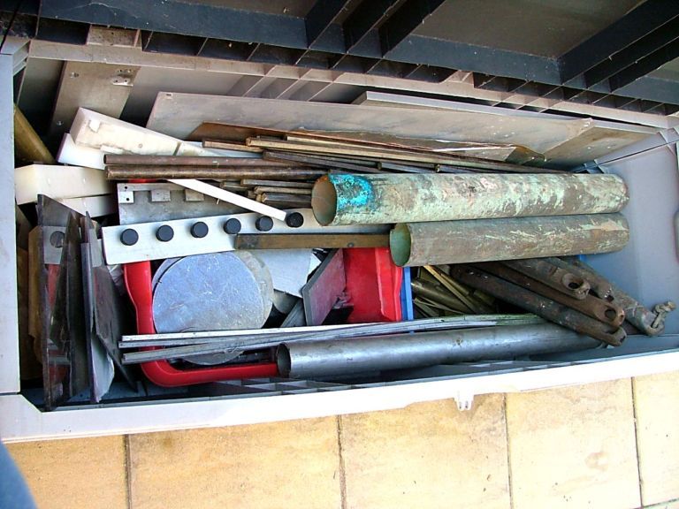
This first pic shows my outside stash, all obtained from either the recycling yard or friends donations, the copper tubes on top are about 4" diameter, plus my sash weights which supply most of my cast iron.
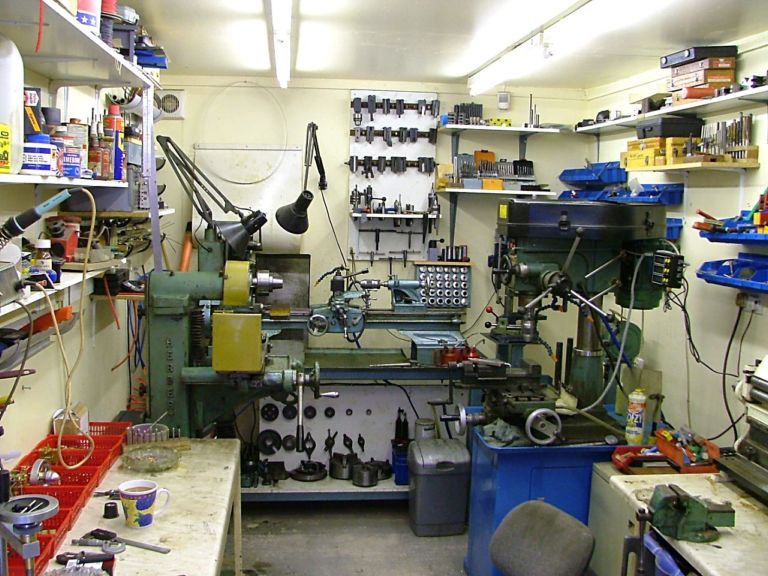
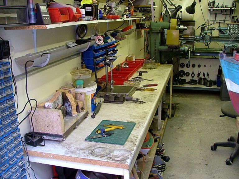
This next shot is coming in from the door, notice not a lot of room. the machinery consists of, on the left a 1960's Herbert surface grinder, in the middle an Atlas 10F 42" bed lathe and on the right a standard type mill drill with a cheap 3 axis DRO fitted. I have to go sideways thru the gap and usually end up with watering eyes because the handles reach parts other handles don't.
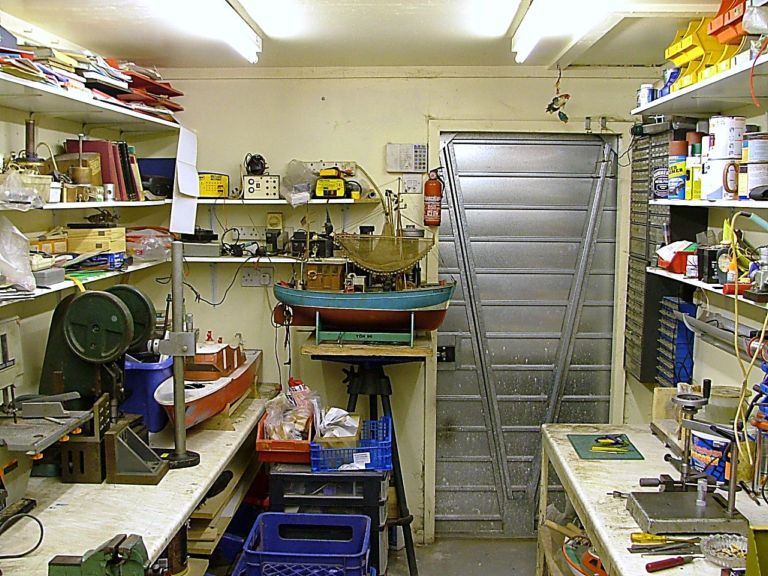
This one shows the shop from the machinery end with the metal prep area on the left and build area on the right.
Bit of a closer view of the metal prep area plus my inside stash on the bottom shelves.
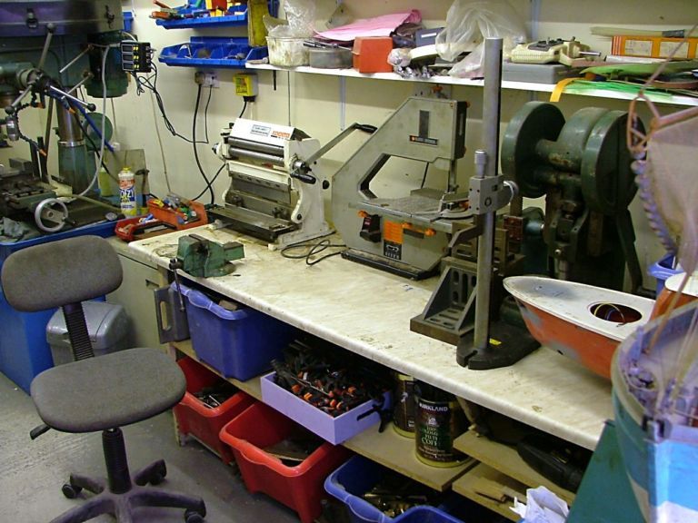
Build area consists of a small brazing/heat treatment area plus a marking out area. Next along is another marking area with my tapping stand followed by the engine build area.
This last shot is my workhorse, The Atlas 10F lathe, nearly 70 years old, but I have brought it right up to date by fitting a Timken roller bearing head, Myford resettable dials, quick change toolpost plus loads of other small modifications. This lathe is now super accurate, especially since I fitted a 5c collet chuck.

About the green press with the flywheels, he says:
It is called a toggle press.
It is hand operated but the 'flywheels' help to make for a very strong punching press. With a correctly angled punch, 3/16" brass sheet is punched straight thru. I use it mainly for blanking out brass and copper discs and pressure assembly of parts.
Not many about nowadays, but if you can get hold of any old stuff, snap their hands off.
firebird posted about his on HMEM. Here's one photo:
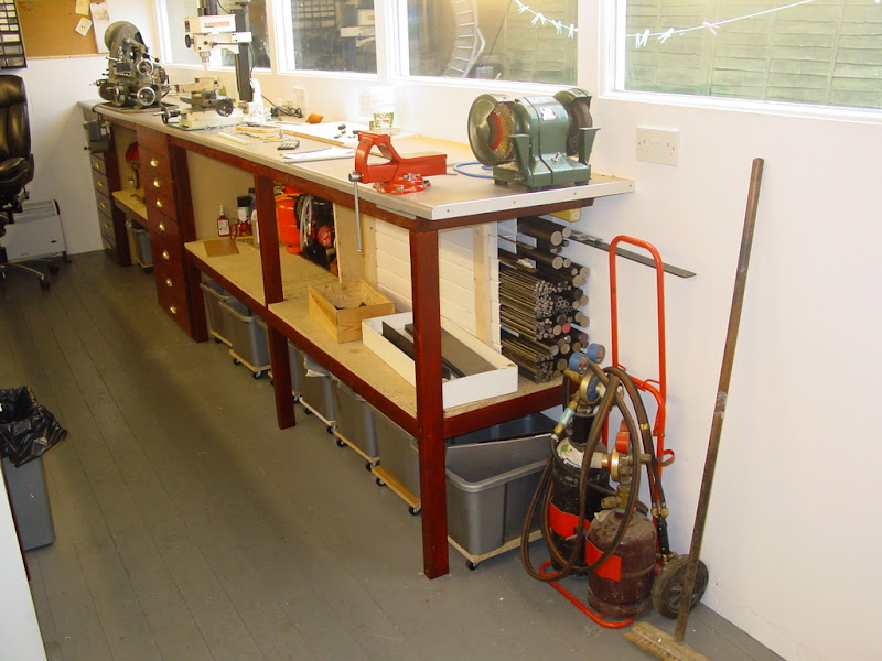
There's two things I particularly like about this. First is his long stock storage under the bench. The other is the containers he has on casters under the bench. Very effective use of space.
Bogstandard posted the following about his shop on the HMEM board:
Here is a little insight into how I do things. First off I built a prefabricated sectional concrete workshop, 16ft x 9ft internal measurement after first laying a 6" thick concrete base, then fully lined the inside and ceiling with 2" insulation board faced with plaster. This keeps me warm in the winter with just a small fan heater.
This first pic shows my outside stash, all obtained from either the recycling yard or friends donations, the copper tubes on top are about 4" diameter, plus my sash weights which supply most of my cast iron.

This next shot is coming in from the door, notice not a lot of room. the machinery consists of, on the left a 1960's Herbert surface grinder, in the middle an Atlas 10F 42" bed lathe and on the right a standard type mill drill with a cheap 3 axis DRO fitted. I have to go sideways thru the gap and usually end up with watering eyes because the handles reach parts other handles don't.

This one shows the shop from the machinery end with the metal prep area on the left and build area on the right.

Bit of a closer view of the metal prep area plus my inside stash on the bottom shelves.

Build area consists of a small brazing/heat treatment area plus a marking out area. Next along is another marking area with my tapping stand followed by the engine build area.

This last shot is my workhorse, The Atlas 10F lathe, nearly 70 years old, but I have brought it right up to date by fitting a Timken roller bearing head, Myford resettable dials, quick change toolpost plus loads of other small modifications. This lathe is now super accurate, especially since I fitted a 5c collet chuck.

About the green press with the flywheels, he says:
It is called a toggle press.
It is hand operated but the 'flywheels' help to make for a very strong punching press. With a correctly angled punch, 3/16" brass sheet is punched straight thru. I use it mainly for blanking out brass and copper discs and pressure assembly of parts.
Not many about nowadays, but if you can get hold of any old stuff, snap their hands off.
firebird posted about his on HMEM. Here's one photo:

There's two things I particularly like about this. First is his long stock storage under the bench. The other is the containers he has on casters under the bench. Very effective use of space.
Thursday, February 28, 2008
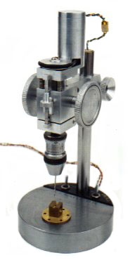
Sensitive drill press
For drilling smaller holes, a sensitive drill press is handy.
Jerry Howell has plans for a Mini drill press

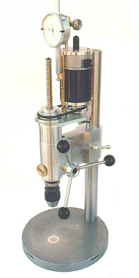
and a Micro drill press
Some YouTube videos of a mini drill press:
Video 1
Video 2
Video 3
There's also a sensitive drilling table in Projects 1 by Village Press:

And then there's George Thomas' Universal Pillar Tool.
Building links here and here.
The following ME articles are the ones I could find regarding the UPT:
Castings were bought eons ago, maybe Power Model Supply when they were around? can't remember. They are still available I believe, check with model engineering suppliers. While cast iron is nice, you could make the whole thing from bar stock like i did the drill head.
Andy, here how i made the D shape. take a piece of brass, say 3/8 dia. Boring the bottom 1/2" to the D's ID radius, milling a section a away, soldering on a flat piece. now, back to the lathe, and turn the OD to neatly drop into a bore in the brass handle and solder (or loctite). if you look at the pics you can see the the lines that shows these fabrication. Hard to explain the drill mechanism with a reasonable amount of typing and my camera is currently busted. I'll take some detailed pics when i can. basically there's a gimbal with a bearing at the top with a radial groove in it. two pins in the gimbal fit into this groove (you can see them in the last pic),
Norm, I have that book, always thought it was basically a reprint of Thomas's two other books? anyway, I like it. Also, years ago HSM did a excellent build article that appears in one of the project books. There'd be minimal welding if you didn't make from castings, for example the arms could be machined from say 1.5 x 1.5 steel stock. Our be luxurious and get some Durabar.
The other note i'd make is I went with peened over tommy bars throughout. This is a departure from the traditional ball handle which is more difficult to make and by many's standards the 'right' way to do it. imo the tommy bars are superior as the can be operate from two positions and there are lots of pinch point set ups where this is a real advantage, the traditional charm of ball handles not withstanding.
LizardKing posted the following:
For all the Americans interested in one of these, I bought a full set of castings from http://www.martinmodel.com/ a few months ago.
Quality if really good and he does have more at around $100 plus shipping for a set which includes 2 arms, table, base, and drill head.
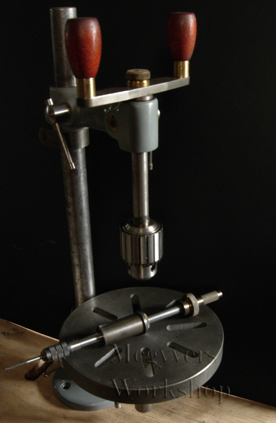
Mcgyver posted again about his UPT on HSM showing it's use for stamping metal: you're right, how many otherwise great looking tools look amateur hour with crooked stamping. A friend who apprenticed at GM recalls a 2 week stint in the stamping shop....no one came out of there not being able to stamp straight. How do you get to Carnegie hall? practice practice practice not wanting to spend two weeks practicing, there's Geo Thomas's UPT which has a great component to it, a square holed holder with detent balls and springs so the punches don't drop out. Clamp a fence to the table and by hand slide the work along for perfectly aligned stampings. Any two pieces of metal together can form the corner....figure out how to hold the corner above table with fence and away you go. Here's some pics of a recent project just for fun - using the UPT clamped to the mill table to mark graduated dials
aligning things


punching
results...things more or less straight!
Jerry Howell has plans for a Mini drill press


and a Micro drill press

Some YouTube videos of a mini drill press:
Video 1
Video 2
Video 3
There's also a sensitive drilling table in Projects 1 by Village Press:


And then there's George Thomas' Universal Pillar Tool.
Building links here and here.
The following ME articles are the ones I could find regarding the UPT:
Vol Issue Page # Title Subject
140 3501 1104 1 Tapping machine and staking tool - General arrangement
140 3502 1165 2 Tapping machine and staking tool - Arms & spindles
140 3503 1209 3 Tapping machine and staking tool - Staking tool
141 3510 351 4 Tapping machine and staking tool - Further details
142 3548 1078 5 Tapping machine and staking tool - More details
142 3549 1149 6 Tapping machine and staking tool - More details
146 3647 1504 1 Mini Drill for Tapping and Staking Tool - Introduction
147 3648 12 2 Mini Drill for Tapping and Staking Tool - Main arrangement
147 3649 86 3 Mini Drill for Tapping and Staking Tool - Sleeves
147 3650 143 4 Mini Drill for Tapping and Staking Tool - Feed lever
147 3651 218 5 Mini Drill for Tapping and Staking Tool - Handle
147 3652 295 6 Mini Drill for Tapping and Staking Tool - Conclusion
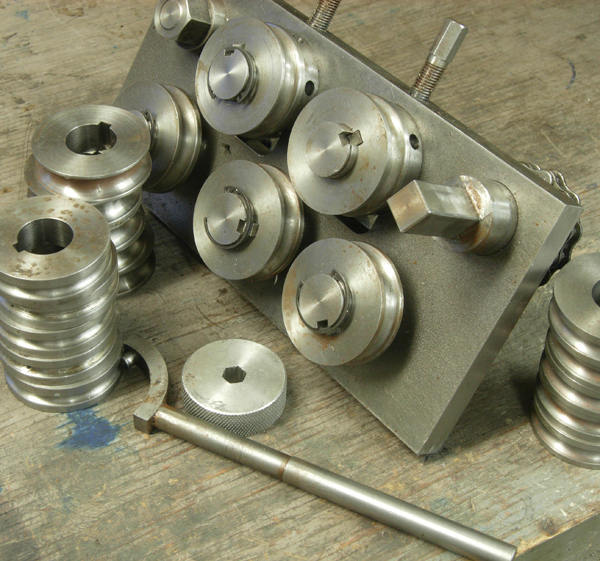
Mcgyver posted about his UPT on the HSM and the HMEM forums:
hadn't posted many pics lately, so a few weeks ago i snapped up a bunch of my UPTI experimented a bit with the photos – its just a black piece of cardboard with the shop lights off and sunlight through a window. Camera is a P&S Nikon P3 (I affectionately call it my POS P&S). It does have the advantage over other P&S that you can control aperture. Everything is done with a tripod and no flash. I also put my name on each pic, what the heck, I made ‘em
The project is the Universal Pillar Tool, a classic designed by George Thomas. I went full bore and made all the accessories including the sensitive drill head.
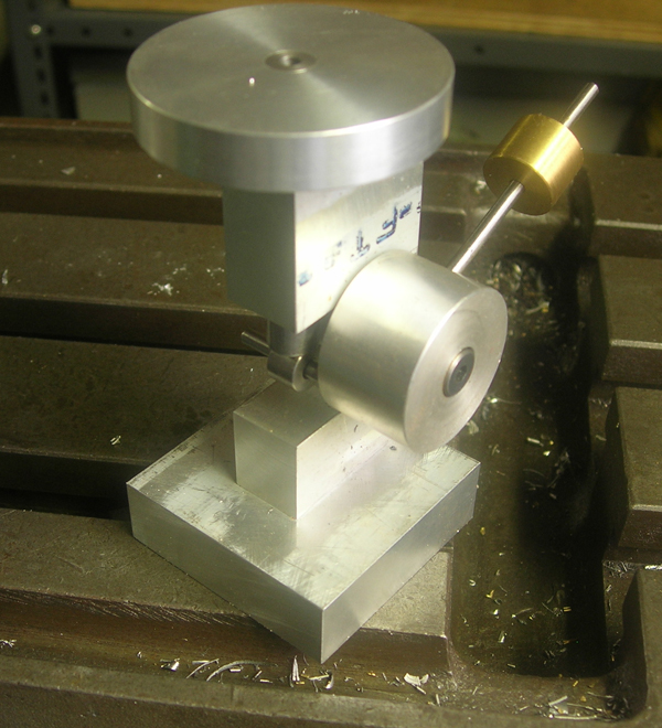
Here’s a smaller tapping head. For the newer guys, not breaking taps depends on keeping them straight so this tool is very handy. I used the end off an Eclipse pin vice of some sort, but still had to make a collet to fit common small tap dia. The bushing in the arm has a small spring underneath the threaded brass cap that presses light on the rod – very handy as the tapping head stays where you leave it and doesn’t fall into the work.

Here’s a close of the small tapping head handle showing the “D” coupling. This is my design and gives and positive drive without having to tighten anything. It’s a snug fit, won’t fall off accidentally.

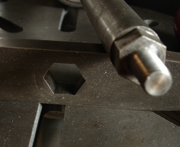
Here’s a larger tapping head
It’s handle is held on by a hex I laid out and hand filed. I’d heard filing hex’s that fit perfectly in each position was the sort thing they’d assign apprentices to teach them to file so thought it would be a good test. It fits amazingly well, the secret is to use a bit of blue as you’re getting close and be very specific about where you are removing material
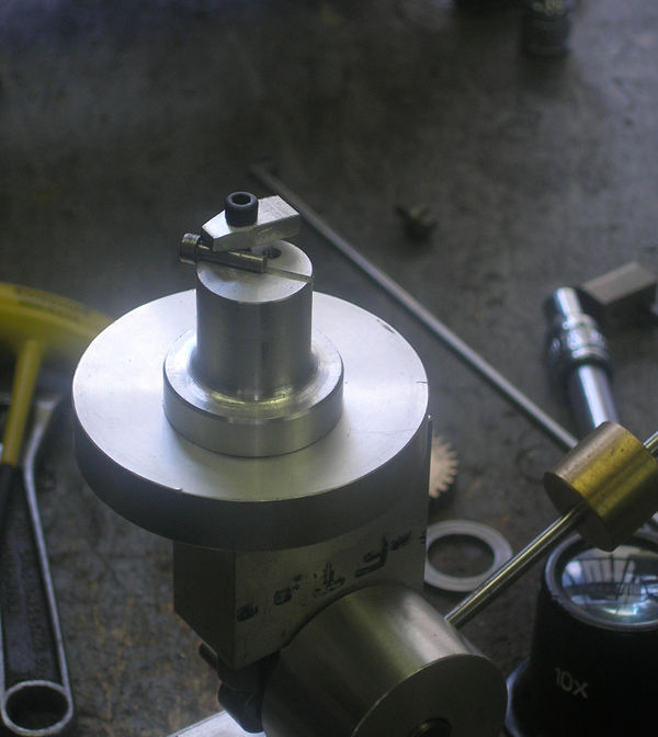
Reconfigured a bit, the tool becomes a staking/riveting tool. Here a couple of blank tools are shown.
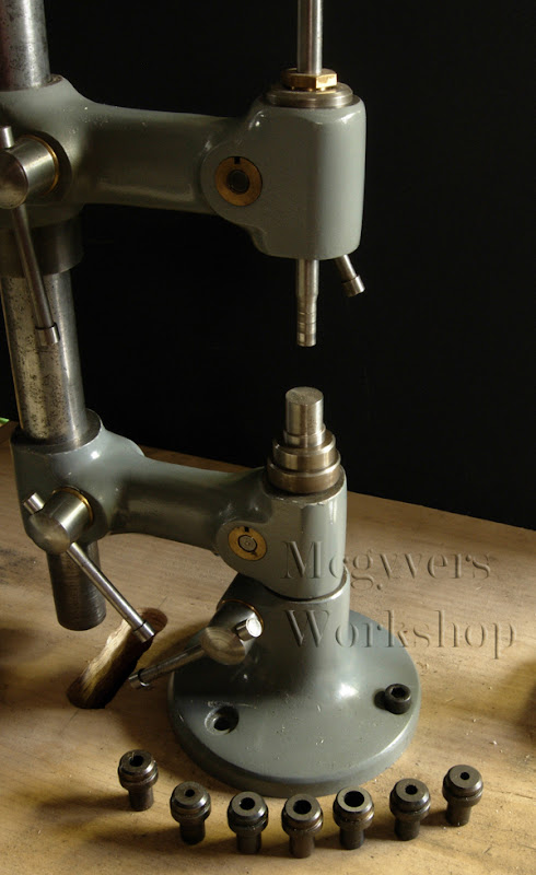
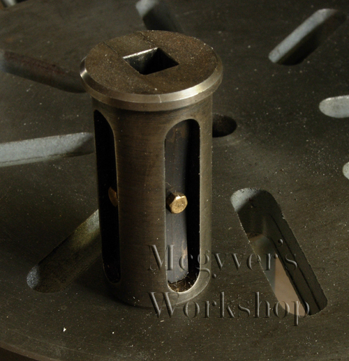
Similarly, a square bushing holds number/letter stamps

The bushing for the square punches is interesting – there are two springs with detent balls underneath to hold the punches in place – a very nice feature!
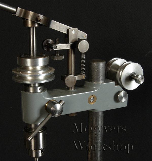
The most complex accessory is the drill head. It works very well and is a pleasure to use. There is an extra casting for this kit but they wanted a fortune for it so I carved my own.
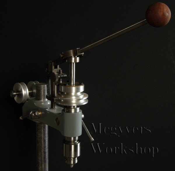
Here’s a close up.
Lot’s of accessories to make. This photo’s a little dark, I still need more exposure experimentation I guess. Most of the staking/punching tools are made but not yet hardened.

It resides in an old drawer with a lid. Hey at least it keeps the condensation off. One day a better made box will get done
Hope that was of interest


Castings were bought eons ago, maybe Power Model Supply when they were around? can't remember. They are still available I believe, check with model engineering suppliers. While cast iron is nice, you could make the whole thing from bar stock like i did the drill head.
Andy, here how i made the D shape. take a piece of brass, say 3/8 dia. Boring the bottom 1/2" to the D's ID radius, milling a section a away, soldering on a flat piece. now, back to the lathe, and turn the OD to neatly drop into a bore in the brass handle and solder (or loctite). if you look at the pics you can see the the lines that shows these fabrication. Hard to explain the drill mechanism with a reasonable amount of typing and my camera is currently busted. I'll take some detailed pics when i can. basically there's a gimbal with a bearing at the top with a radial groove in it. two pins in the gimbal fit into this groove (you can see them in the last pic),
Norm, I have that book, always thought it was basically a reprint of Thomas's two other books? anyway, I like it. Also, years ago HSM did a excellent build article that appears in one of the project books. There'd be minimal welding if you didn't make from castings, for example the arms could be machined from say 1.5 x 1.5 steel stock. Our be luxurious and get some Durabar.
The other note i'd make is I went with peened over tommy bars throughout. This is a departure from the traditional ball handle which is more difficult to make and by many's standards the 'right' way to do it. imo the tommy bars are superior as the can be operate from two positions and there are lots of pinch point set ups where this is a real advantage, the traditional charm of ball handles not withstanding.
LizardKing posted the following:
For all the Americans interested in one of these, I bought a full set of castings from http://www.martinmodel.com/ a few months ago.
Quality if really good and he does have more at around $100 plus shipping for a set which includes 2 arms, table, base, and drill head.
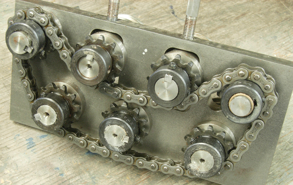
Mcgyver posted again about his UPT on HSM showing it's use for stamping metal: you're right, how many otherwise great looking tools look amateur hour with crooked stamping. A friend who apprenticed at GM recalls a 2 week stint in the stamping shop....no one came out of there not being able to stamp straight. How do you get to Carnegie hall? practice practice practice not wanting to spend two weeks practicing, there's Geo Thomas's UPT which has a great component to it, a square holed holder with detent balls and springs so the punches don't drop out. Clamp a fence to the table and by hand slide the work along for perfectly aligned stampings. Any two pieces of metal together can form the corner....figure out how to hold the corner above table with fence and away you go. Here's some pics of a recent project just for fun - using the UPT clamped to the mill table to mark graduated dials
aligning things
punching
results...things more or less straight!
Tuesday, February 26, 2008
Heat treating furnace
A few links on building a furnace:
http://www.britishblades.com/home/articles.php?action=show&showarticle=31
http://www.knifeforums.com/forums/showtopic.php?tid/752668/post/775813/hl//
referencing:
here and here.
And lastly, a post on the HSM forum.
http://www.britishblades.com/home/articles.php?action=show&showarticle=31
http://www.knifeforums.com/forums/showtopic.php?tid/752668/post/775813/hl//
referencing:
here and here.
And lastly, a post on the HSM forum.
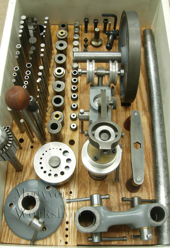
Tubing bender and unbender
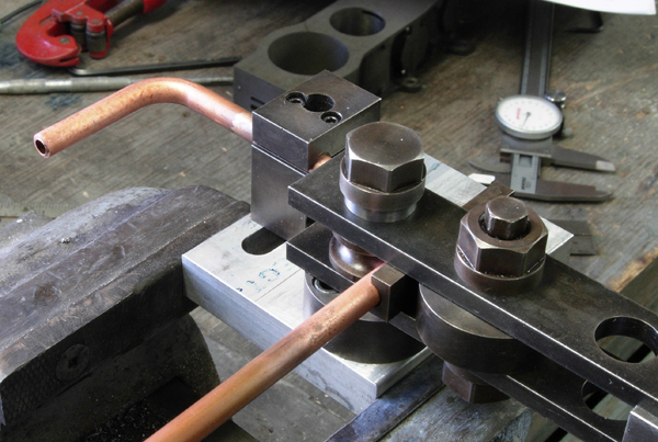
Mcgyver posted on the HSM forum a tubing bender and unbender he made:
I made this a few years, ago but used it today and have never taken photos of it so thought you guys might like to see it.
occasionally when making models, one has to bend copper tubing. the typical tube bender, while successful in creating a bend, is not up to the task for modeling as 1) it won't work to a small enough radius and/or 2) distorts the shape of tubing around the curve - ie not a smooth transition from curve to straight on both the inside and outside curves. Thus began a bunch of experiments and reading on to produce a decent bend in a tube.
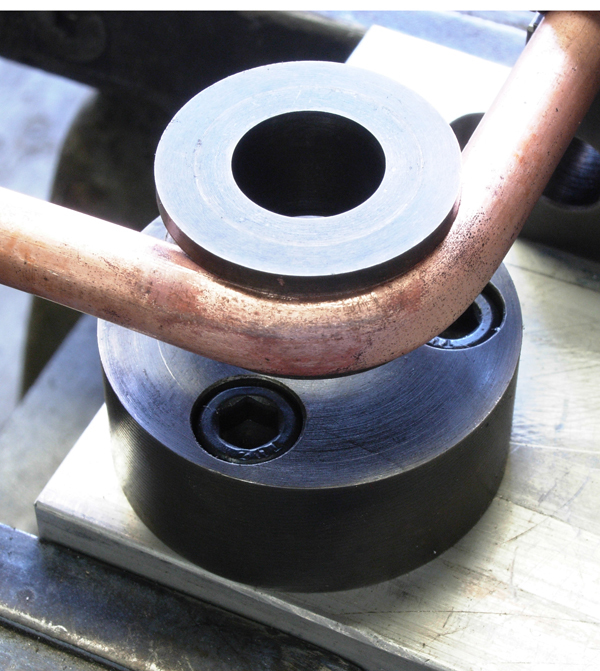
What I came up with has two unique (well they were to me anyway) features. 1) the outside die, rather than being a round die like the inner is straight. 2) the outside, straight, die, gets tightly pressed against the inner die, sandwiching the copper tube between them. This done via an eccentric axle. If you look in the pic, you’ll see the straight die, then a cylindrical spacer. It's this cylindrical spacer that is on an eccentric shaft.
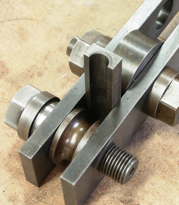
Here a bend is being set up. The tube clamp shows a larger allen key setting the orientation of the clamp along a tee slot, while the smaller one clamps the tube itself. I made slit spacers for different sized tubing. In the main pivt, about the round die, there are spacers such that it is firmly bolted to the base, yet free rotate.
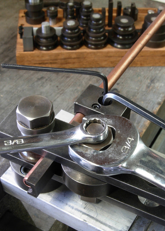
here's a shot after completing the first and second bends. the tube was annealed for these bends
here's a close up showing the fairly decent shape that is maintained. ideally the bend looks like 1/4 of a torus without kinks or ploughed-up leading edge to the bend.
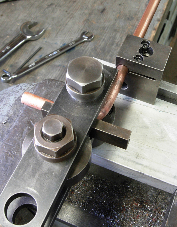
of course, if you're going to make a tube bender, you're going to do so for all sizes of tubes and radii. Should I ever commit a heinous crime, I consider this important work towards my insanity defense. It handles tubing from 1/8 to 3/8 by 16th’s
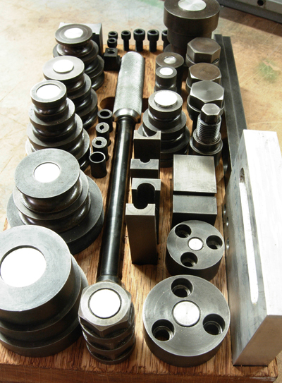
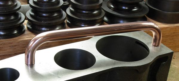
after cutting to length and some emery and polish work, here's the finished product. It’s sitting on the block to which it will one day be attached. Imo it turned our well, its a .5" centre radius bend in a 5/16 tubing. Still, the Stuart plans (this is for a triple expansion) calls for a 5/16 centre line bend, the accomplishment of which still eludes me, even with this rig. perhaps filling with cerro or something.
nothing is hardened, figured its low duty cycle and bending copper. I will probably use casenit on some parts, ie the top 3/8 hex on the pivot is starting to get dinged up. The finish is just the wipe on blue done to help fight rust.
here's the device i used to cut the radii. hardened a bit of drill rod with a clearance taper to it and then after hardening, surface ground it down to be the right dia. it work reasonably well, had I known about the 'up and over' style using a boring head and tangential cutter, might have gone that route

the tube comes in coils which isn't much good for my purposes. you can straighten it by tieing one end off to a tree and the other to a bumper, but that reduces the dia and is a pita in my urban environment (I'm sure the neighbors already think I'm certifiable, let alone if they keep seeing me out tying crap to a tree and to my car).
so i made this mill. the two upper rollers are adjustable. orginally they locked into position via a threaded collar and spanner (shown in the pic) however this wasn't positive enough so i added the hex screws to keep them in place. the middle roller, while it has a sprocket, pretty much idles. it works well and is powered used the table crank from my mill.
here's a few shots of it

I made this a few years, ago but used it today and have never taken photos of it so thought you guys might like to see it.
occasionally when making models, one has to bend copper tubing. the typical tube bender, while successful in creating a bend, is not up to the task for modeling as 1) it won't work to a small enough radius and/or 2) distorts the shape of tubing around the curve - ie not a smooth transition from curve to straight on both the inside and outside curves. Thus began a bunch of experiments and reading on to produce a decent bend in a tube.
What I came up with has two unique (well they were to me anyway) features. 1) the outside die, rather than being a round die like the inner is straight. 2) the outside, straight, die, gets tightly pressed against the inner die, sandwiching the copper tube between them. This done via an eccentric axle. If you look in the pic, you’ll see the straight die, then a cylindrical spacer. It's this cylindrical spacer that is on an eccentric shaft.

Here a bend is being set up. The tube clamp shows a larger allen key setting the orientation of the clamp along a tee slot, while the smaller one clamps the tube itself. I made slit spacers for different sized tubing. In the main pivt, about the round die, there are spacers such that it is firmly bolted to the base, yet free rotate.

here's a shot after completing the first and second bends. the tube was annealed for these bends


here's a close up showing the fairly decent shape that is maintained. ideally the bend looks like 1/4 of a torus without kinks or ploughed-up leading edge to the bend.

of course, if you're going to make a tube bender, you're going to do so for all sizes of tubes and radii. Should I ever commit a heinous crime, I consider this important work towards my insanity defense. It handles tubing from 1/8 to 3/8 by 16th’s

after cutting to length and some emery and polish work, here's the finished product. It’s sitting on the block to which it will one day be attached. Imo it turned our well, its a .5" centre radius bend in a 5/16 tubing. Still, the Stuart plans (this is for a triple expansion) calls for a 5/16 centre line bend, the accomplishment of which still eludes me, even with this rig. perhaps filling with cerro or something.

nothing is hardened, figured its low duty cycle and bending copper. I will probably use casenit on some parts, ie the top 3/8 hex on the pivot is starting to get dinged up. The finish is just the wipe on blue done to help fight rust.
here's the device i used to cut the radii. hardened a bit of drill rod with a clearance taper to it and then after hardening, surface ground it down to be the right dia. it work reasonably well, had I known about the 'up and over' style using a boring head and tangential cutter, might have gone that route

the tube comes in coils which isn't much good for my purposes. you can straighten it by tieing one end off to a tree and the other to a bumper, but that reduces the dia and is a pita in my urban environment (I'm sure the neighbors already think I'm certifiable, let alone if they keep seeing me out tying crap to a tree and to my car).
so i made this mill. the two upper rollers are adjustable. orginally they locked into position via a threaded collar and spanner (shown in the pic) however this wasn't positive enough so i added the hex screws to keep them in place. the middle roller, while it has a sprocket, pretty much idles. it works well and is powered used the table crank from my mill.
here's a few shots of it


Lathe carriage stops
A few ideas for lathe carriage stops/indicator holders:
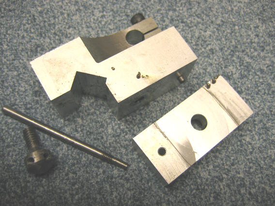
Daryl Bane posted this one:
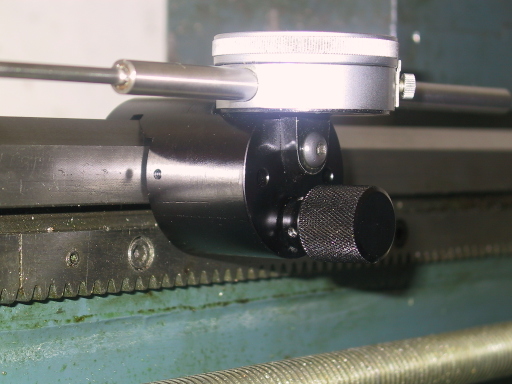
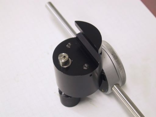
It clamps using a retractable eccentric pin. A quick twist of the knob will lock it and if you pull the knob the whole thing can be lifted away.
J Tiers posted this:
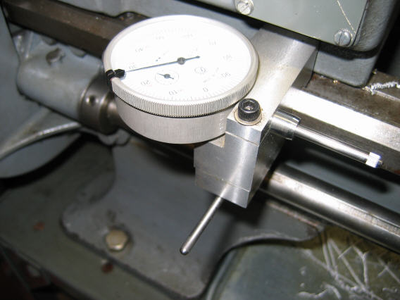
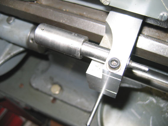
One poster suggested cannibalizing a HF micrometer to use for the depth stop.
Daryl Bane posted this one:


It clamps using a retractable eccentric pin. A quick twist of the knob will lock it and if you pull the knob the whole thing can be lifted away.
J Tiers posted this:


One poster suggested cannibalizing a HF micrometer to use for the depth stop.
Subscribe to:
Posts (Atom)