Just a list of things that I've seen that I think would be handy to have in the shop.
Cam action drill press vise
squirt bottle for lubricant for hole drilling
table covers that fit around the vise on the mill and keep swarf out of the t-slot
Monday, November 3, 2008
Thursday, October 30, 2008
Transfer screws
I've seen transfer screw made from bolts and such, but I came across a reference to Heimann transfer screws and I think they're neat.
The transfer screws have a small hex at the base of the point.

The screws nest together inside the wrench/holder. Note that there must be a hole in the back of the transfer screws for the point of the one behind it to slide into it. The end of the wrench has a hex broached into to it. The top cap screws off.

The size of the transfer screws is stamped into the wrench/holder.

I'm not sure if this last one is shopmade or not. But, it almost looks like the end is a socket head cap screw. Would probably be easier to attach one of those to the end for the hex socket than to broach the hex in the end of the holder.
The transfer screws have a small hex at the base of the point.
The screws nest together inside the wrench/holder. Note that there must be a hole in the back of the transfer screws for the point of the one behind it to slide into it. The end of the wrench has a hex broached into to it. The top cap screws off.
The size of the transfer screws is stamped into the wrench/holder.
I'm not sure if this last one is shopmade or not. But, it almost looks like the end is a socket head cap screw. Would probably be easier to attach one of those to the end for the hex socket than to broach the hex in the end of the holder.

Friday, October 24, 2008
Dust collector
My surface grinder makes a lot of dust. If I want it to coexist nicely with the rest of my machines, a dust collector is a must. Holescreek posted some photos and a description of his on Practical Machinist:
Several members of this board (myself included) have posed questions as to what everyone else uses for grinding dust control in their home shop. I read the few threads in the archives on both boards and ended up with more questions than answers. Most of the web sites I googled cater to wood dust.
In my little home shop I have one surface grinder, a couple of snag grinders, and a small belt sander that I use only for metal. The surface grinder was my primary concern so I based all of my requirements for dust collection on it. I watched industrial Torit type units on Ebay for several months hoping that I could snag one close enough to home to pick up myself and save freight. Not having a forklift to unload a semi is one drawback, then having to either buy yet another VFD or change a motor out was another.
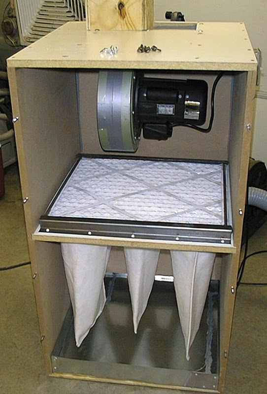
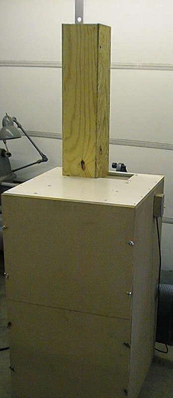
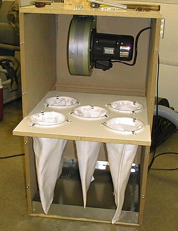
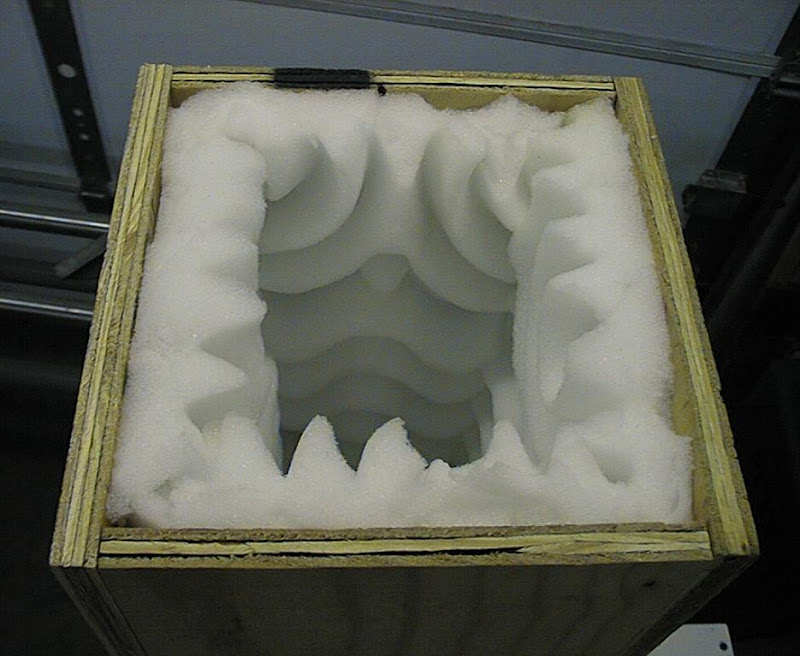
I refined my list of requirements to fit my wants: single phase, fine filtration, mobile, quiet, safe (from fires) and CHEAP. My wants pretty much decimated the majority of dust collectors available on the net. A friend gave me an old furnace blower so I started prototyping a dust collector around it. I figured that I'd just start trying stuff. I pulled the covers off of a Torit #64 at work to see what they did. To make a long story short, the furnace fan wasn't feasible (but it was quiet) without using a 10" duct. I was about ready to give up when I found a damaged 650CFM HF dust collector on Ebay for $30. I wasn't going to use the broken part anyway, and it was about an hour drive each way to get it. The noise that it made measured out at 95dB sitting on the floor. Putting it in the box I had left from my furnace blower attempt dropped it to 85dB and adding the insulated exhaust stack took it down to a manageable 75dB. Since this is a prototype I figure that I'll remake it out of steel on a smaller scale to fit the HF impeller later on. I used MDF for the current case. I know it can burn, but I often use MDF for impromptu welding jigs and seldom do I ever get a flame from stick welding directly against it. I've got around $50 in everything so far, and the suction is very strong. The 5 filter bags were picked up at a local flea market. I found them in the McMaster catalog as polyester filter bags rated at 25 gallons/min. I think the catalog had the mesh size at around 2-3 micron. I held a piece of filter over a butane flame and it melted but would not catch fire. I added the close weave furnace filter on top for good measure, and the whole tray slides out for maintenance. I’m sure there’s a few things I can come up with to improve on it, from what I’ve read, I could use a lot more surface area on the filter bags. I’m open to suggestions from the group.
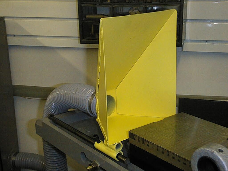
Matt Isserstedt had the following to add:
Wondering if a large 90 degree square "elbow" on the exhaust stack would further reduce the noise level.
The egg-crate/waffle foam is a wonderful idea, however noise that radiates "straight up" can still escape...if there were another foam surface directly above that might absorb some more. Might be able to accomplish the same thing with a "cone hat" type of cap lined with the foam and then exhaust air escapes 360 degrees around. Thinking somewhat like the drip cap on a fireplace's chimney.
Several members of this board (myself included) have posed questions as to what everyone else uses for grinding dust control in their home shop. I read the few threads in the archives on both boards and ended up with more questions than answers. Most of the web sites I googled cater to wood dust.
In my little home shop I have one surface grinder, a couple of snag grinders, and a small belt sander that I use only for metal. The surface grinder was my primary concern so I based all of my requirements for dust collection on it. I watched industrial Torit type units on Ebay for several months hoping that I could snag one close enough to home to pick up myself and save freight. Not having a forklift to unload a semi is one drawback, then having to either buy yet another VFD or change a motor out was another.
I refined my list of requirements to fit my wants: single phase, fine filtration, mobile, quiet, safe (from fires) and CHEAP. My wants pretty much decimated the majority of dust collectors available on the net. A friend gave me an old furnace blower so I started prototyping a dust collector around it. I figured that I'd just start trying stuff. I pulled the covers off of a Torit #64 at work to see what they did. To make a long story short, the furnace fan wasn't feasible (but it was quiet) without using a 10" duct. I was about ready to give up when I found a damaged 650CFM HF dust collector on Ebay for $30. I wasn't going to use the broken part anyway, and it was about an hour drive each way to get it. The noise that it made measured out at 95dB sitting on the floor. Putting it in the box I had left from my furnace blower attempt dropped it to 85dB and adding the insulated exhaust stack took it down to a manageable 75dB. Since this is a prototype I figure that I'll remake it out of steel on a smaller scale to fit the HF impeller later on. I used MDF for the current case. I know it can burn, but I often use MDF for impromptu welding jigs and seldom do I ever get a flame from stick welding directly against it. I've got around $50 in everything so far, and the suction is very strong. The 5 filter bags were picked up at a local flea market. I found them in the McMaster catalog as polyester filter bags rated at 25 gallons/min. I think the catalog had the mesh size at around 2-3 micron. I held a piece of filter over a butane flame and it melted but would not catch fire. I added the close weave furnace filter on top for good measure, and the whole tray slides out for maintenance. I’m sure there’s a few things I can come up with to improve on it, from what I’ve read, I could use a lot more surface area on the filter bags. I’m open to suggestions from the group.
Matt Isserstedt had the following to add:
Wondering if a large 90 degree square "elbow" on the exhaust stack would further reduce the noise level.
The egg-crate/waffle foam is a wonderful idea, however noise that radiates "straight up" can still escape...if there were another foam surface directly above that might absorb some more. Might be able to accomplish the same thing with a "cone hat" type of cap lined with the foam and then exhaust air escapes 360 degrees around. Thinking somewhat like the drip cap on a fireplace's chimney.
Monday, June 2, 2008
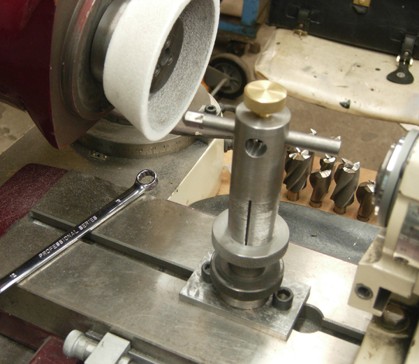
Dressing tool holder
Mcgvyer posted on the HSM forum about his tool to hold a dressing tool on the grinder:
the known uses, to me anyway, for taper threads went up 50% with this project. Buffing wheel arbors, pipe threads and my tapered thread collect contraption!
been sharpening a lot of end mills lately and have been frustrated at the frequent dressing required AND having to take the end mill out of the holder and mount the wheel dresser.
I wanted a quick, no wrenches way to mount the dresser without altering the set up.
Base plate gets bolted to the table with a short stub, not too many turns to thread the column on. at first the column had a T bolt but it was tough on the table, scratching it each time it was taken on and off because there is inevitably grit between the two. The column screws onto the base plate, knurled ring fits the key way and used to tighten, then drops out of the way. that idea works OK, handy but probably not worth the extra effort, larger OD with knurling near the base would have sufficed
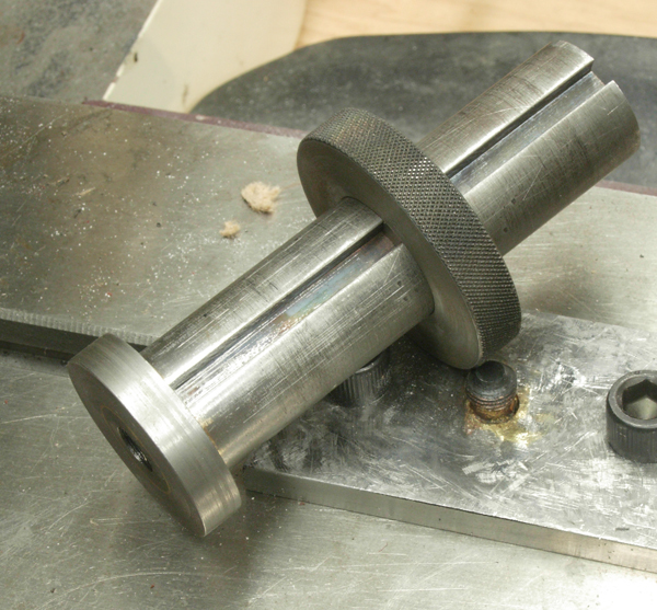
the head that holds the dresser has a taper cut thread and is bored and slit like a collet. tighten up the collar and it looks into place. pretty simple, but works well.
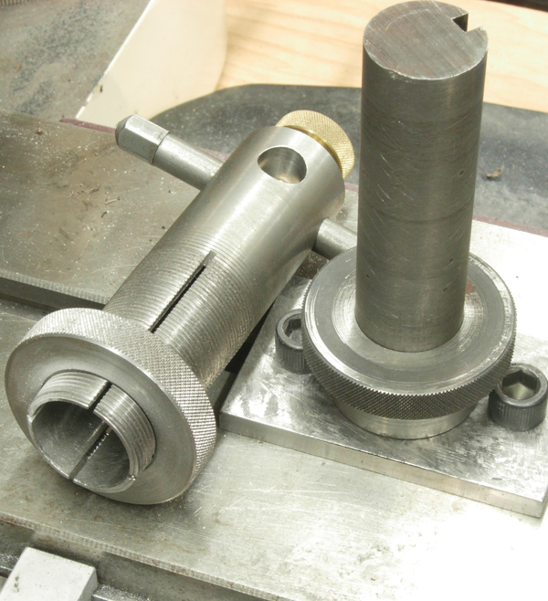
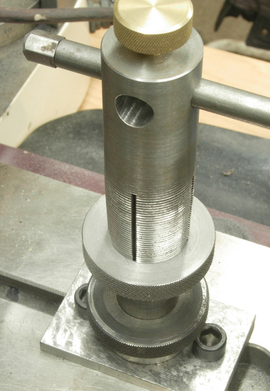
The threaded part, the head I'll call gets clamped via the collet action on the column. Aside from the easy on/off the collet gives, it lets you quickly install it at whatever height you want and pointing in any direction, you just put it at what ever height/direction you want and tighten the ring. feed and doc of the diamond is via the table's control x/y. here's a shot with a little more perspective, you can see the air spindle to the right.
the known uses, to me anyway, for taper threads went up 50% with this project. Buffing wheel arbors, pipe threads and my tapered thread collect contraption!
been sharpening a lot of end mills lately and have been frustrated at the frequent dressing required AND having to take the end mill out of the holder and mount the wheel dresser.
I wanted a quick, no wrenches way to mount the dresser without altering the set up.
Base plate gets bolted to the table with a short stub, not too many turns to thread the column on. at first the column had a T bolt but it was tough on the table, scratching it each time it was taken on and off because there is inevitably grit between the two. The column screws onto the base plate, knurled ring fits the key way and used to tighten, then drops out of the way. that idea works OK, handy but probably not worth the extra effort, larger OD with knurling near the base would have sufficed
the head that holds the dresser has a taper cut thread and is bored and slit like a collet. tighten up the collar and it looks into place. pretty simple, but works well.
The threaded part, the head I'll call gets clamped via the collet action on the column. Aside from the easy on/off the collet gives, it lets you quickly install it at whatever height you want and pointing in any direction, you just put it at what ever height/direction you want and tighten the ring. feed and doc of the diamond is via the table's control x/y. here's a shot with a little more perspective, you can see the air spindle to the right.
Clamp for bandsaw
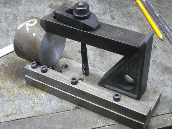
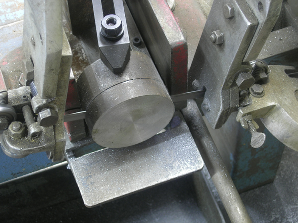
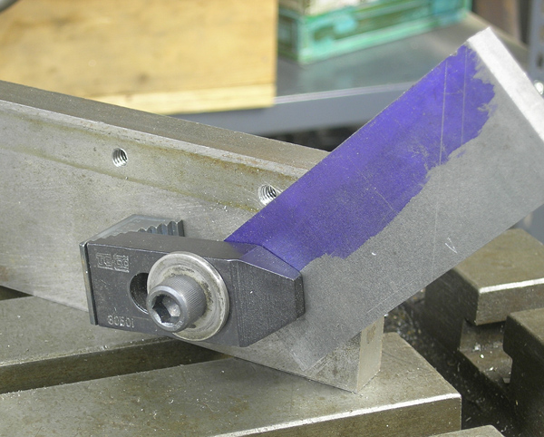
Mcgyver posted on the HSM forum his nifty little clamp for holding small pieces in his saw:
I was doing some work today and shot some pictures of an device I made years ago that is so simple, I almost can't call it a device. If you divided usefulness by ease of construction, it's got a huge payback.
The problem is 1) horizontal bandsaws can have the jaws pushed out of square if the clamping force is all on one side and 2) short piece are difficult to hold properly in the bandsaw vice.
All this is is a piece of crs with some holes tapped to fit my strap clamp bolts and a stop to align the work against. One shot is taking a 5/8" disk of a very short piece of 2.625 stock, the other is saving a bunch of hack sawing using the device in vertical position cutting a piece of 1/2" CR at an angle (its barely visible but I did mill a flat so the blade would start properly). Both of these jobs are a real pita without such a device.
I was doing some work today and shot some pictures of an device I made years ago that is so simple, I almost can't call it a device. If you divided usefulness by ease of construction, it's got a huge payback.
The problem is 1) horizontal bandsaws can have the jaws pushed out of square if the clamping force is all on one side and 2) short piece are difficult to hold properly in the bandsaw vice.
All this is is a piece of crs with some holes tapped to fit my strap clamp bolts and a stop to align the work against. One shot is taking a 5/8" disk of a very short piece of 2.625 stock, the other is saving a bunch of hack sawing using the device in vertical position cutting a piece of 1/2" CR at an angle (its barely visible but I did mill a flat so the blade would start properly). Both of these jobs are a real pita without such a device.
Sheet Metal Tank
Mcgyver posted on the HSM forum about building a tank for a hit and miss engine:
Needed to make a brass gas tank for my hit & miss engine and thought you guys might like some pictures. Experts might find the photo's superfluous, but I tried to take enough that it's a bit of a how-to post for someone newer
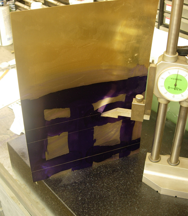
Lazy mans way of laying out the sheet - propped up against an angle plate, the height gauge makes quick work of the layout. Brass is .028 thou.
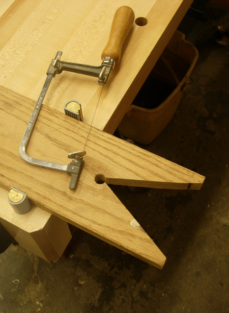
A lot of the corner material can be cut with good shears, but as the corners will have tabs, you need to get into them with a fret saw. Here's the simple set up for this job
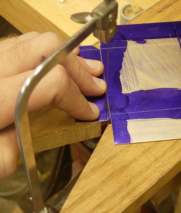
Cutting out the corner with a fret saw
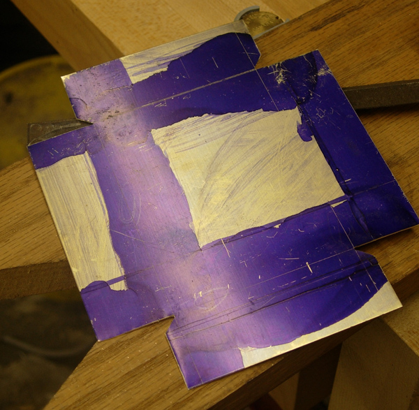
The sheet is now ready for folding. Corners all cleaned out and any required touchups done with a file
Here the sheet metal is held in a home made set of folding bars - just crs, some dowel pins and cap screws.
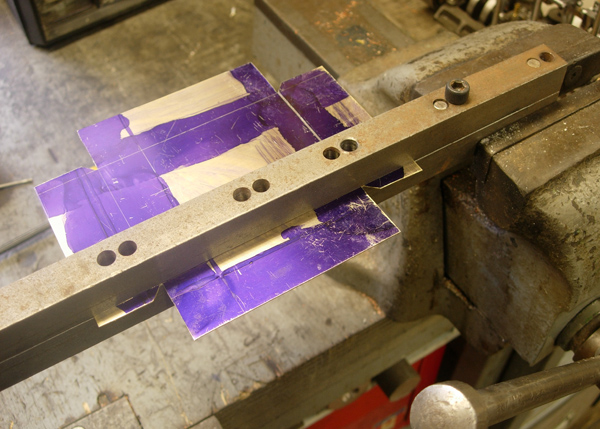
In the midst of the first fold - I held the bars vertically as the wasn't enough throat distance in the vice to hold horizontally - a more convenient position. Note that the tabs are not folded over at this setting of the bars
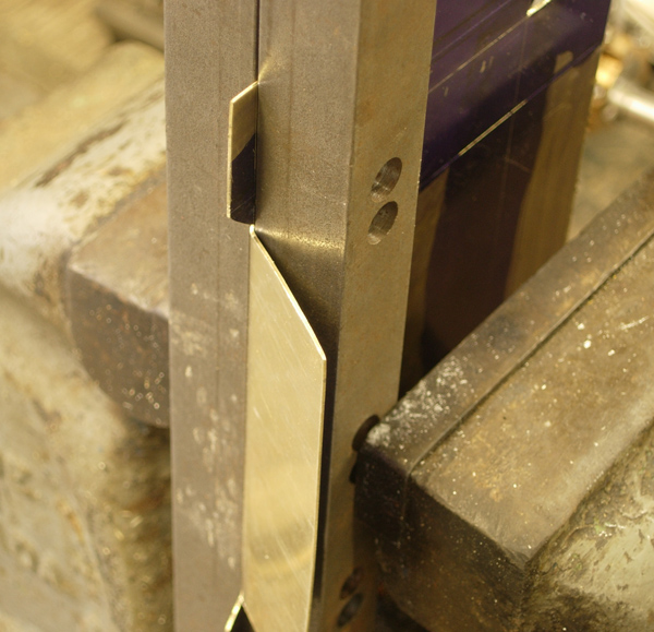
This is the right tool for folding the metal over so as to not mare the surface; a leather mallet
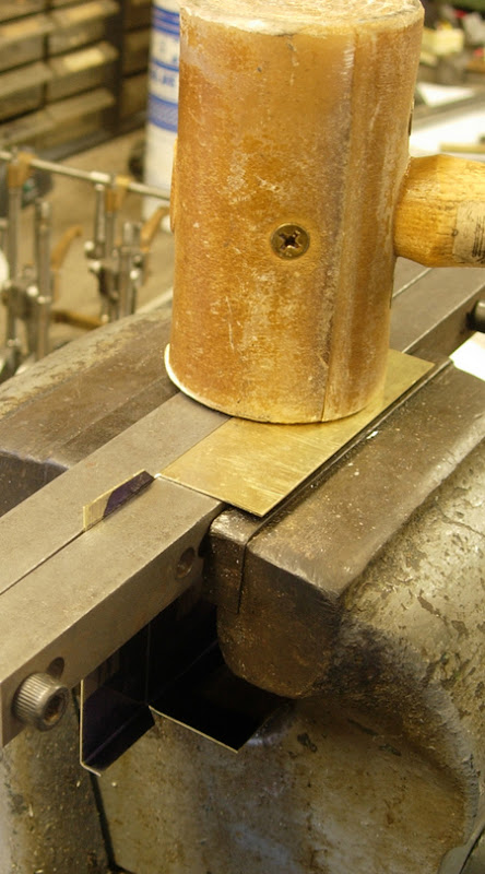
Here is a tab that has just been folded. Note how the bars have been moved so that there is about a 1/32 gap between the bar and the side - this will allow the tab to fold up inside the of the side
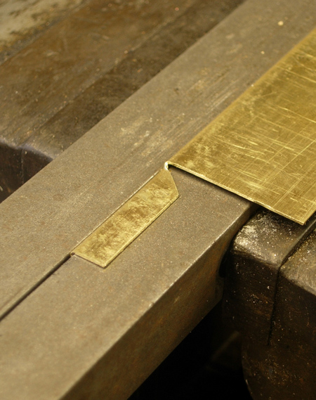
Here the work piece is ready to have the ends folded.
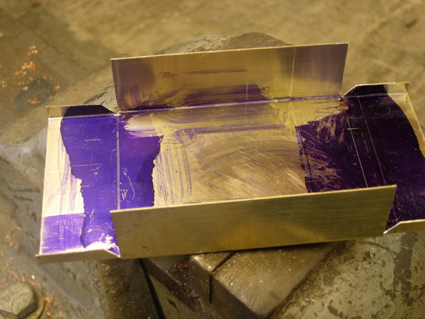
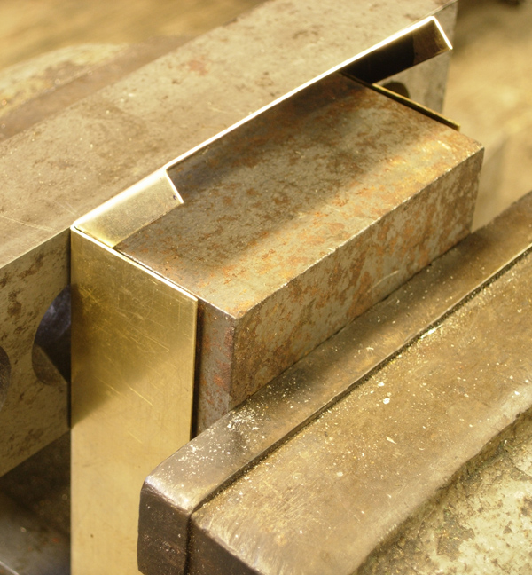
Hunt through the scrap box for a chunk of metal to fold against and that will fit in side of the box. Here the end is being folded. Note how the tabs tuck neatly inside of the box.
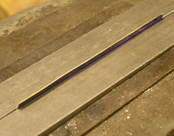
The narrow lip on the bottom piece is folding using the folding bars
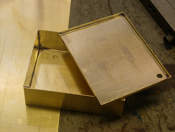
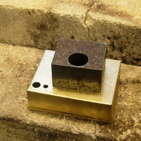
Here's the competed sheet metal work, ready for soldering
Simple solder set up, weight & refractory bricks. Wet paper towel was used as a heat sink around completed joints.
Here a some shots of the competed tank. I had wanted to include shots of bending the pipes and shots of them set up for soldering, but I managed to destroy my camera (arrrg). Bought a new one for these final shots. The pipes were soldering using my 3rd hand design http://bbs.homeshopmachinist.net//Fo...ML/012958.html
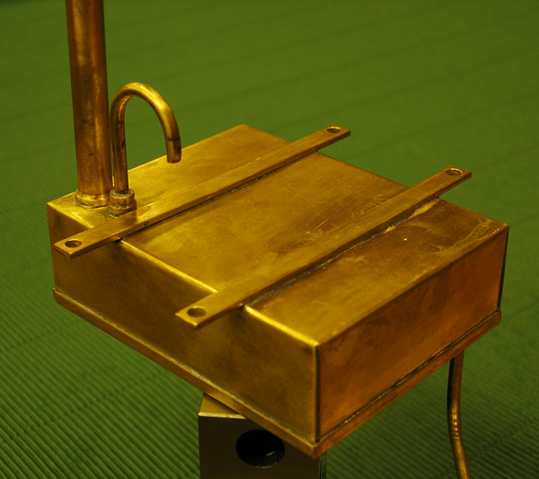
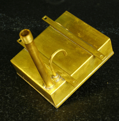
Hope its of some value to you
Needed to make a brass gas tank for my hit & miss engine and thought you guys might like some pictures. Experts might find the photo's superfluous, but I tried to take enough that it's a bit of a how-to post for someone newer
Lazy mans way of laying out the sheet - propped up against an angle plate, the height gauge makes quick work of the layout. Brass is .028 thou.
A lot of the corner material can be cut with good shears, but as the corners will have tabs, you need to get into them with a fret saw. Here's the simple set up for this job
Cutting out the corner with a fret saw
The sheet is now ready for folding. Corners all cleaned out and any required touchups done with a file
Here the sheet metal is held in a home made set of folding bars - just crs, some dowel pins and cap screws.
In the midst of the first fold - I held the bars vertically as the wasn't enough throat distance in the vice to hold horizontally - a more convenient position. Note that the tabs are not folded over at this setting of the bars
This is the right tool for folding the metal over so as to not mare the surface; a leather mallet
Here is a tab that has just been folded. Note how the bars have been moved so that there is about a 1/32 gap between the bar and the side - this will allow the tab to fold up inside the of the side
Here the work piece is ready to have the ends folded.
Hunt through the scrap box for a chunk of metal to fold against and that will fit in side of the box. Here the end is being folded. Note how the tabs tuck neatly inside of the box.
The narrow lip on the bottom piece is folding using the folding bars
Here's the competed sheet metal work, ready for soldering
Simple solder set up, weight & refractory bricks. Wet paper towel was used as a heat sink around completed joints.
Here a some shots of the competed tank. I had wanted to include shots of bending the pipes and shots of them set up for soldering, but I managed to destroy my camera (arrrg). Bought a new one for these final shots. The pipes were soldering using my 3rd hand design http://bbs.homeshopmachinist.net//Fo...ML/012958.html
Hope its of some value to you
Grinding wheel balancer
Mcgyver posted on the HSM forum about repairing a grinding wheel balancer, and included a link to an article on how to build one:
I recently came into possession of a grinding wheel balancer, and having fun with the digital camera, recorded the exploits. Prior to, I didn't know much about balancing grinding wheels so thought that maybe posting on it would help some people. The basics i learned via Jan Rowland's article at
http://www.homemetalshopclub.org/news/sep04/sep04.html
some good info there on making your own.
It may or may not help on a bench grinder but on the T&C cutter grinder or surface grinder it can make a real difference.
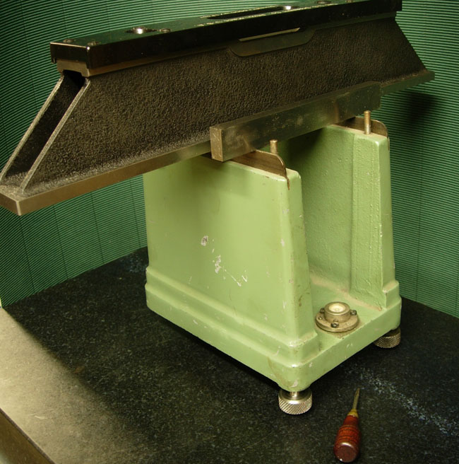
Here's a nice balancer that came my way. I was surprised to find its metric, $38 for metric die to make a new foot that was hopelessly bent.

I barely had enough room to start a tap with making extensions and once started had to use a wrench. The pillar tool is used to make this awkward start straight.
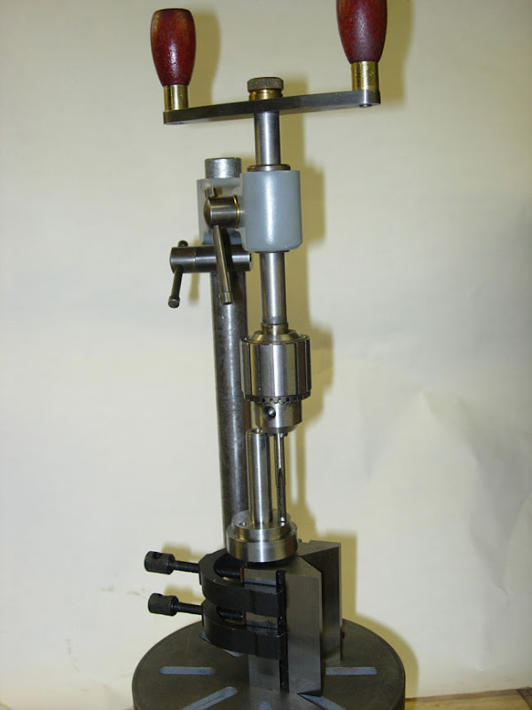
here's the finished arbor. I must have had a hole go slightly off or some thing as the plate shown need a tiny bit of balancing itself.

next it's the balancing weights. I made them from two thicknesses, .025 and .031. I wanted a very accurate fit on the arbor so that error wouldn't induced between disassembling on the arbor and installation on the grinding spindle. The four sheet metal pieces are sandwiched between a couple of metal plates
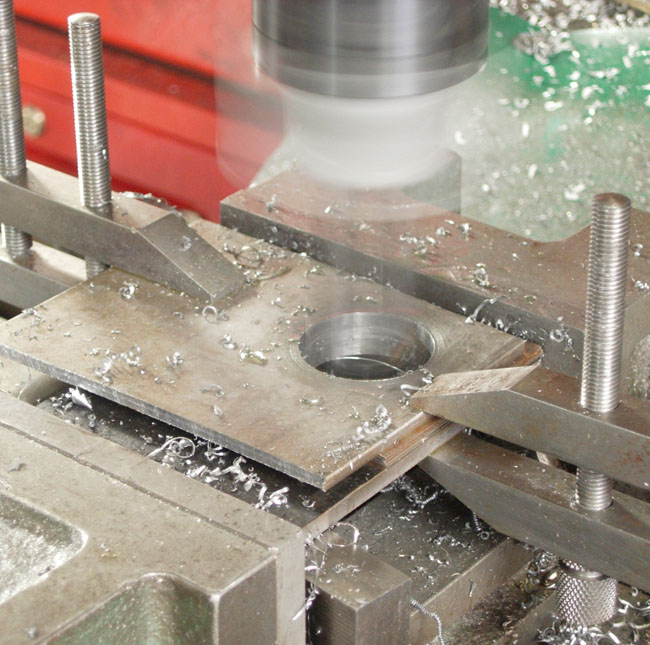
After boring, I laid out, sheared and then filed to shape the weights.
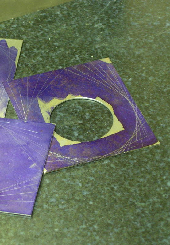
here are the finished weights, identified by number. The number will help get it right when its reassembled on the spindle.

the balancer's got a small internal level. I checked and adjusted this with a precision level, will probably do this each time, the internal level is not super sensitive.
here's a final shot of it in use. The location of each weight is marked on the blotter and then its reassembled on the grinding spindle.
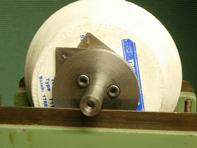
The wheel shown, a 'triumph' which I think is KBC's house brand and was in terrible balance, causing noticeable vibration in the machine and on the cut. After balancing, it runs as smoothly as the spindle does empty!
Here's the article that Mcgyver linked to (actually written by Dick Kostelnicek):
Static Balancing of Grinding Wheels
by Dick Kostelnicek - HMSC Member
What you Need
A 9 x 12 in. surface plate.
A set of 1/4-in. thick parallel pairs.
A precision level.
Two 6 in lengths of undamaged 1/4 in. drill rod.
Super glue and masking tape.
A mandrel or arbor that fits your wheel.
Time and patience
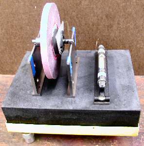
You can statically balance vitrified grinding wheels for both your surface and pedestal grinders with a few common shop tools. Don't worry about dynamic balancing. These wheels don't need it since they are large in diameter compared to the axial thickness and they don't change shape when turning at rated speed. First, build two arbor supports from pieces of ground parallels, as shown in the photo below. I place a very small drop of super glue on each end of a parallel as I stack them on top of one another. Later, you can disassemble them by breaking the glue bond and cleaning the residue with acetone, an excellent solvent for cyanoacrylate glue. Use masking tape (colored blue in the photo} to secure the drill rod to the top of each stack. The round drill rods prevent the sharpness of the edges on the parallels from interfering with the free wheeling of the wheel arbor. Also, debris will be easily squeezed out from under the arbor while rolling on a round rather than a flat surface. Make sure the surface plate is perfectly level in both directions. My plate is supported in a metal frame that has three adjustable screw feet, making it easy to level.

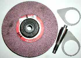
Surface Grinding Wheels First, dress the wheel while mounted on the machine for which it is to be used. This will guarantee that it is round, a necessary step for new, inexpensive, or damaged wheels. Then, mount it on a dummy tapered arbor (see photo below). For balancers, I use a pair of thin spring shims. They are made from 1/8-in. aliminum sheet, split at the bottom of the large hole, and clamp over the wheel hub.
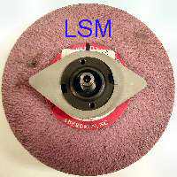
Now, place the wheel arbor on the two supports and allow it to settle to its heavy point (without shims). Mark the high spot of the wheel, calling it the light side mark or LSM, on the edge of the round paper blotter. Then, mount the two shims with their projections perpendicular to the LSM as seen in the photo below.
Rotate both shims in opposite directions a few degrees toward the LSM. Roll the wheel so that the LSM is parallel to the surface plate, and let it settle to its heavy side, photo below.

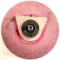
If the LSM is still on top, move both shims closer to the LSM until the wheel will not rotate when the LSM is turned parallel to the surface plate. Some times you may not rotate both shims by the exact same amount in opposite directions. Then the LSM may not be at the top or bottom after the wheel settles. In that case, move just one of the shims to reset the LSM vertical. This will take some practice, as you will always choose the wrong shim to move or move it in the wrong direction. When the wheel stops rotating at an arbitrary point, well almost any point because you have to stop when it is good enough, then you are done, as seen in the photo below.
Pedestal Grinding wheels The photo below shows an 8-in. pedestal grinding wheel to be balanced. I use a lathe mandrel having a very slight tapered, but that is of no consequence here, to support the wheel and its metal wheel flanges during balancing. I've lightened up one side of each flange by drilling a few holes near the edge. Now the side without holes is the heavy side of the flange and plays the same role as the weighty projection of the clamp-on flanges discussed above in reference to surface grinding wheels. Here, however, you must place one flange on each side of the wheel. Just as discussed above, start without flanges to determine and mark the light side or LSM of the wheel. Place the flanges against opposite sides of the wheel so that the lightening holes are along a line parallel to the surface plate and facing toward opposite sides of the wheel. Now proceed to counter rotate both flanges so the lightening holes move away and downward from the LSM. Stop when the wheel settles at an arbitrary point.
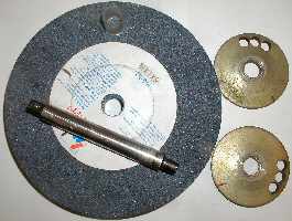
Witness mark the flange against the LSM on each side of the wheel as seen in the photo below. Finally mount the wheel and its flanges on the machine's arbor and spin it up to speed for a test run.
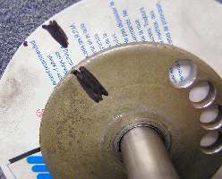
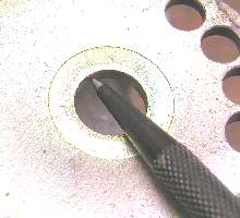
Now, as will often happen, the wheel flanges will not be snug on the dummy arbor during balancing. They may try to always settle to their heavy side while you are rotating the wheel. You may not notice the slippage of the flange as the wheel is rocking to and fro. This can lead to great frustration. Solve this problem by putting a bit of chewing gum between the flange and the wheel. Or better yet, upset the inside of the flange arbor holes with a prick punch as seen in the photo below. Either of these two methods will provide enough friction and prevent the flange from rotating relative to the grinding wheel on its own.
I hope your wheels run with reduced vibration. You may even see less waviness on the surface finish of the items produced on your surface grinder.
I recently came into possession of a grinding wheel balancer, and having fun with the digital camera, recorded the exploits. Prior to, I didn't know much about balancing grinding wheels so thought that maybe posting on it would help some people. The basics i learned via Jan Rowland's article at
http://www.homemetalshopclub.org/news/sep04/sep04.html
some good info there on making your own.
It may or may not help on a bench grinder but on the T&C cutter grinder or surface grinder it can make a real difference.
Here's a nice balancer that came my way. I was surprised to find its metric, $38 for metric die to make a new foot that was hopelessly bent.

I barely had enough room to start a tap with making extensions and once started had to use a wrench. The pillar tool is used to make this awkward start straight.
here's the finished arbor. I must have had a hole go slightly off or some thing as the plate shown need a tiny bit of balancing itself.

next it's the balancing weights. I made them from two thicknesses, .025 and .031. I wanted a very accurate fit on the arbor so that error wouldn't induced between disassembling on the arbor and installation on the grinding spindle. The four sheet metal pieces are sandwiched between a couple of metal plates
After boring, I laid out, sheared and then filed to shape the weights.
here are the finished weights, identified by number. The number will help get it right when its reassembled on the spindle.

the balancer's got a small internal level. I checked and adjusted this with a precision level, will probably do this each time, the internal level is not super sensitive.
here's a final shot of it in use. The location of each weight is marked on the blotter and then its reassembled on the grinding spindle.
The wheel shown, a 'triumph' which I think is KBC's house brand and was in terrible balance, causing noticeable vibration in the machine and on the cut. After balancing, it runs as smoothly as the spindle does empty!
Here's the article that Mcgyver linked to (actually written by Dick Kostelnicek):
Static Balancing of Grinding Wheels
by Dick Kostelnicek - HMSC Member
What you Need
A 9 x 12 in. surface plate.
A set of 1/4-in. thick parallel pairs.
A precision level.
Two 6 in lengths of undamaged 1/4 in. drill rod.
Super glue and masking tape.
A mandrel or arbor that fits your wheel.
Time and patience
You can statically balance vitrified grinding wheels for both your surface and pedestal grinders with a few common shop tools. Don't worry about dynamic balancing. These wheels don't need it since they are large in diameter compared to the axial thickness and they don't change shape when turning at rated speed. First, build two arbor supports from pieces of ground parallels, as shown in the photo below. I place a very small drop of super glue on each end of a parallel as I stack them on top of one another. Later, you can disassemble them by breaking the glue bond and cleaning the residue with acetone, an excellent solvent for cyanoacrylate glue. Use masking tape (colored blue in the photo} to secure the drill rod to the top of each stack. The round drill rods prevent the sharpness of the edges on the parallels from interfering with the free wheeling of the wheel arbor. Also, debris will be easily squeezed out from under the arbor while rolling on a round rather than a flat surface. Make sure the surface plate is perfectly level in both directions. My plate is supported in a metal frame that has three adjustable screw feet, making it easy to level.

Surface Grinding Wheels First, dress the wheel while mounted on the machine for which it is to be used. This will guarantee that it is round, a necessary step for new, inexpensive, or damaged wheels. Then, mount it on a dummy tapered arbor (see photo below). For balancers, I use a pair of thin spring shims. They are made from 1/8-in. aliminum sheet, split at the bottom of the large hole, and clamp over the wheel hub.
Now, place the wheel arbor on the two supports and allow it to settle to its heavy point (without shims). Mark the high spot of the wheel, calling it the light side mark or LSM, on the edge of the round paper blotter. Then, mount the two shims with their projections perpendicular to the LSM as seen in the photo below.
Rotate both shims in opposite directions a few degrees toward the LSM. Roll the wheel so that the LSM is parallel to the surface plate, and let it settle to its heavy side, photo below.

If the LSM is still on top, move both shims closer to the LSM until the wheel will not rotate when the LSM is turned parallel to the surface plate. Some times you may not rotate both shims by the exact same amount in opposite directions. Then the LSM may not be at the top or bottom after the wheel settles. In that case, move just one of the shims to reset the LSM vertical. This will take some practice, as you will always choose the wrong shim to move or move it in the wrong direction. When the wheel stops rotating at an arbitrary point, well almost any point because you have to stop when it is good enough, then you are done, as seen in the photo below.
Pedestal Grinding wheels The photo below shows an 8-in. pedestal grinding wheel to be balanced. I use a lathe mandrel having a very slight tapered, but that is of no consequence here, to support the wheel and its metal wheel flanges during balancing. I've lightened up one side of each flange by drilling a few holes near the edge. Now the side without holes is the heavy side of the flange and plays the same role as the weighty projection of the clamp-on flanges discussed above in reference to surface grinding wheels. Here, however, you must place one flange on each side of the wheel. Just as discussed above, start without flanges to determine and mark the light side or LSM of the wheel. Place the flanges against opposite sides of the wheel so that the lightening holes are along a line parallel to the surface plate and facing toward opposite sides of the wheel. Now proceed to counter rotate both flanges so the lightening holes move away and downward from the LSM. Stop when the wheel settles at an arbitrary point.
Witness mark the flange against the LSM on each side of the wheel as seen in the photo below. Finally mount the wheel and its flanges on the machine's arbor and spin it up to speed for a test run.
Now, as will often happen, the wheel flanges will not be snug on the dummy arbor during balancing. They may try to always settle to their heavy side while you are rotating the wheel. You may not notice the slippage of the flange as the wheel is rocking to and fro. This can lead to great frustration. Solve this problem by putting a bit of chewing gum between the flange and the wheel. Or better yet, upset the inside of the flange arbor holes with a prick punch as seen in the photo below. Either of these two methods will provide enough friction and prevent the flange from rotating relative to the grinding wheel on its own.
I hope your wheels run with reduced vibration. You may even see less waviness on the surface finish of the items produced on your surface grinder.
Subscribe to:
Posts (Atom)